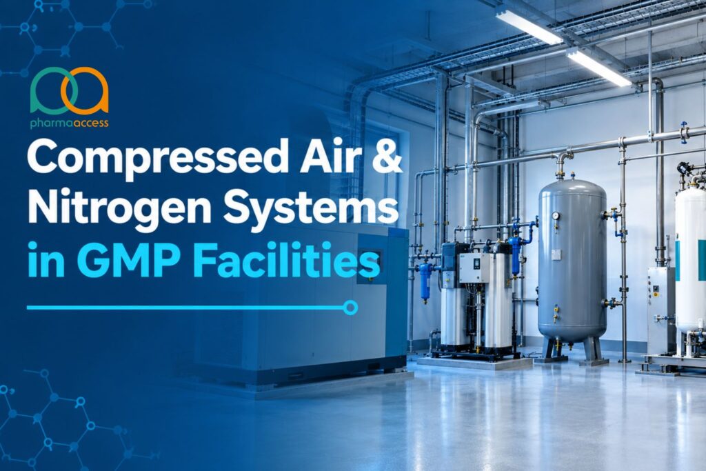
Compressed air sounds harmless. It is invisible, it is widely used and can be overlooked during early utility planning. But it dries vials, moves powder, sprays coatings, and drives valves in the same rooms where product is open. Nitrogen blankets vessels; lines are flushed. When either gas contacts the product, it becomes an ingredient in the quality story.
This guide describes the design, specification, monitoring, and qualification of compressed air and nitrogen systems that meet defined pharmaceutical GMP requirements. We believe in engineering choices based on the intended use. Here’s why they each matter. Let’s take a look.
Plant Air vs Clean Compressed Air Pharma Sites Should Separate
Not every air line needs the same gas quality. Treating them all the same can increase costs; treating the wrong one lightly can compromise product quality.
Begin with a system impact assessment. Label each use:
- No product contact (plant or instrument air): actuators, pneumatic tools, valve control, general utilities.
- Potential environmental impact: air exhausted from pneumatic equipment into areas where product or product-contact surfaces are exposed.
- Direct contact (process air and nitrogen): air or nitrogen in contact with the product, product-contact surfaces, vials or ampoules.
No product contact does not automatically mean no quality impact; assess the effects of utility failure on critical process controls and the manufacturing environment.
Typical direct-impact uses include spraying tablet coatings, drying products or product-contact surfaces, cleaning and drying equipment, suspending API during milling, and blanketing API vessels with nitrogen. A use-based approach avoids applying the highest specification to every line, as this can add cost without improving product protection.
Quality requirements for direct-contact gases should be defined. Plant air needs an appropriate, documented specification.
GMP Expectations for Pharmaceutical Process Gases
GMP rules do not give a universal specification for compressed air. You define it from the intended use, and then you prove it.
Three points to explain the attention:
- The expectation is given in Annex 1. EU GMP Annex 1 for sterile manufacturing states that gases contacting product or primary-container surfaces should have the appropriate chemical, particulate, and microbial quality.
- Specifications and qualification matter. Documented specifications, qualification and GMP controls provide evidence that compressed gases are suitable for their intended use.
- Decompression does not sterilise the gas. Normal compression and decompression in process gas systems should not be relied upon to eliminate microorganisms.
Compressed air sampling can also be coordinated with the site’s environmental monitoring and contamination control programmes, where applicable.
Read More: Pharmaceutical Facility CAPEX
Nitrogen System Pharmaceutical Industry Applications
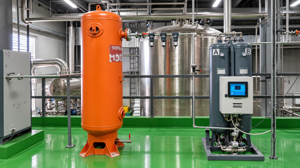
Typically, a nitrogen system in pharmaceutical manufacturing plants performs four jobs:
- Blanketing and overlay: Nitrogen blanketing reduces oxygen exposure for sensitive products in vessels and containers.
- Purge and inert: Nitrogen replaces air from lines, tanks, and filling areas.
- Moving product: Using nitrogen pressure to push liquids through filters and lines.
- Drying: Nitrogen is used for drying product-contact parts, vials, and ampoules.
There are two common central supply arrangements. Nitrogen is produced from compressed air by on-site pressure swing adsorption (PSA) generators. Liquid nitrogen is delivered by tanker, stored in a cryogenic tank and vaporised into the network. Both require defined purity and impurity specifications for the intended use. For PSA, continuous online oxygen and moisture measurement with alarms is commonly used. If nitrogen is delivered, your incoming material procedures may still require that each shipment be release tested.
Additional controls apply to aseptic processing. Nitrogen and air used in aseptic work should be filtered through a sterilising-grade filter with a nominal pore size of no more than 0.22 µm at the point of use.
Nitrogen safety also needs attention. Nitrogen can displace oxygen and create an asphyxiation hazard. Install oxygen monitoring in locations identified by an oxygen-deficiency risk assessment. Review ventilation and safe vent routing in design.
Define the response to off-specification gas, including isolation or diversion where needed.
Compressor Philosophy: Oil-Free, Lubricated, and Redundant
The compressor selection sets the oil risk for the whole network.
- Oil-free compressors reduce the risk of lubricant entering the compressed-air stream. They help control compressor-derived oil contamination. Some “oil-free” machines do contain oil in some components, so read the data sheet and check the claim.
- Lubricated compressors can meet the required gas quality when oil is controlled through appropriate downstream treatment. So the treatment train is a critical control that needs maintenance and verification.
Coalescing filters remove oil aerosols; oil-vapour removal may require adsorption or another suitable treatment.
Next is redundancy. If one compressor or dryer fails, the system should maintain the required gas quality or bring the affected process to a controlled stop. A standby arrangement can include one compressor and one dryer sized to support critical process demand. Piping dryers and filters in parallel can provide redundancy at additional capital cost, and a suitable changeover arrangement can route the required flow through the available qualified train.
Schedule these early, too:
- Place the intake air away from exhaust, solvent vents, and traffic.
- Receiver size to accommodate demand swings
- Assess the need for standby power for compressors, dryers, and alarms that protect product
- Heat-of-compression dryers can reduce drying energy demand on compatible oil-free compressor systems.
Dryers, Dew Point, and Moisture Control
Moisture contamination can contribute to several system problems. It can promote corrosion, clog filters, and support microbial growth. Condensation in a gas filter can cause blockage or support microbial growth.
Moisture can be expressed as pressure dew point (PDP), which is the temperature at which water starts to condense at line pressure. A PDP is not the same as an atmospheric dew point, because dew point changes with gas pressure.
The dryer type determines the achievable dew point:
Refrigerated dryers: typically reach about +3°C PDP, corresponding to ISO 8573-1 water Class 4.
Desiccant dryers: can achieve -40°C or -70°C PDP. Class 2 means a PDP of -40°C or lower, which cannot be achieved with a conventional refrigerated dryer.
Compressed air and nitrogen systems are normally designed and maintained dry, which greatly reduces the potential for microbial growth. The specification should define the required dew point at a stated pressure and a moisture limit appropriate to the intended use. Critical moisture levels are usually monitored online with alarms, and those instruments and alarms are commissioned and qualified where moisture matters.
ISO 8573-1: Understanding Compressed Air Quality Classes
Solid particles, water, and total oil are the three contaminants used by ISO 8573-1 to classify air. The selected classes are listed in a three-part designation in that order. For Classes 1 and above, a lower number generally indicates stricter limits within each contaminant category. A Class 1.2.1 spec means Class 1 for particles, Class 2 for water, and Class 1 for total oil.
An application may specify Class 1.2.1, but no single class combination applies to all pharmaceutical uses. 1.2.1 is an illustrative specification, not a universal GMP requirement. Select and justify the required classes for the intended use. Microbial requirements need separate definitions. ISO 8573-1 does not set a universal pharmaceutical microbial acceptance limit, while ISO 8573-7 provides a microbiological test method. For direct-contact air, add an application-specific microbial requirement and, for aseptic use, a sterilising filter at the point of use.
This table summarises common controls and verification considerations for pharmaceutical process gases:
| Contaminant | Common control | Common monitoring |
| Viable particles | Dry system, sterilising filter (maximum nominal pore size 0.22 µm) at point of use for aseptic applications | Filter integrity testing appropriate to use; periodic microbial sampling according to applicable GMP requirements and risk |
| Non-viable particles | Particulate filters selected to meet the required particle specification close to point of use | Particle testing at representative use points; filter inspection and replacement |
| Moisture | Dryer sized for the target dew point | Online dew point with alarms where critical; verification as specified |
| Oil | Oil-free compressors, coalescing filters and oil-vapour removal where required | Qualification testing and risk-based routine verification, including after relevant changes or invasive work |
| Nitrogen purity | PSA or cryogenic supply design | Purity and impurity checks; online oxygen and moisture monitoring for on-site generation as specified |
Filtration and Point-of-Use Protection
Filters provide point-of-use protection. So place them appropriately.
- Aseptic applications: Use hydrophobic sterilising-grade filters with a nominal pore size of no more than 0.22 µm at the point of use. Define integrity testing by filter criticality and use, including post-use testing of critical sterile gas and vent filters and review with batch release where applicable.
- Non-sterile uses: particulate filters, selected to meet the specified particle limits, generally at or near the point of use or on the supply line. Inspection, verification and replacement requirements should reflect process risk, manufacturer recommendations and operating conditions.
- Location: Locate filters as close to the point of use as possible. The piping can collect particles introduced downstream of a supply-line filter during maintenance.
- Downstream tubing: Sterilise piping or tubing after the filter for sterile service.
A point-of-use filter is no justification for a dirty network. It helps control contamination reaching the product. It cannot compensate for poor distribution design, corrosion or uncontrolled moisture.
Distribution Design: Ring Main, Materials, and Drainage
Air quality problems at the point of use can originate in the pipework. These decisions form part of Pharma Access’s mechanical and utility system design and piping and plumbing design capabilities.
- Layout: A ring main (loop) supplies air from two directions and can improve pressure stability. As the facility expands, unnecessary branches and unused stubs should be minimised. Where condensate could collect, keep drops short and take them from the top of the main so that condensate does not run into equipment.
- Drains and slopes: The piping design should define slope and drainage where condensate can collect. Verify your own design basis, but plan any required slope early because it impacts ceiling space.
- Materials: Piping materials may include stainless steel (304L or 316L), copper or aluminium, subject to gas quality and service requirements. Unsuitable materials or joints can introduce particles, degrade or leak, so check compatibility with pressure, temperature and any cleaning or sterilisation methods. Stainless steel can be suitable for clean-gas systems because it reduces the risk of corrosion-related contamination downstream.
- Cleanliness at Construction: Consider the cutting oils and cleaning agents used in piping construction and maintenance. Perform a clean install and verified cleaning or purging before first use.
- Identification: Colour code and label air and nitrogen lines. Use gas-specific connections to prevent accidental cross-connection.
Provide backflow prevention where reversal from pressure or vacuum systems could pose a risk to product quality.
Monitoring and Sampling
Good monitoring uses a combination of continuous instruments and periodic sampling.
Continuous (online), where required by process risk:
- Pressure in the header and critical branches
- Dew point downstream of dryers
- Differential pressure across filter
- Residual oxygen and moisture in on-site-generated nitrogen
Periodic sampling at the point of use:
- Particles, total oil and moisture, as specified
- Microbial sampling: For process gases within Annex 1’s scope, perform periodic microbial monitoring at the point of use
Sampling locations and frequency should be defined for the specific system. Base them on a documented risk assessment and applicable GMP requirements. Additional testing may be needed following invasive maintenance. Apply the assessed controls: a gas entering an open product in Grade A has different control needs from a gas actuating a valve.
Remember routine care as part of the maintenance plan. The plan should include inspection of the compressor, change of filters, integrity tests on sterile filters, calibration of the monitoring equipment, and leak testing.
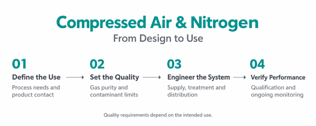
Process Gas Qualification in Pharma: From Design to PQ
Pharma teams follow a documented gas qualification lifecycle. The ISPE Good Practice Guide Process Gases, Second Edition, addresses design review and design qualification, generation, treatment, distribution, redundancy, and monitoring. Specifications are established during engineering design and verified through commissioning and qualification.
A practical sequence might look like this:
- Impact assessment and user requirements: classification of each use and definition of the gas specification.
- Design review and DQ: check compressors, nitrogen supply arrangements, dryers, filters, piping, redundancy, and monitoring requirements.
- Factory and site testing. Check skids and verify piping cleanliness before use.
- IQ: verify materials, welds, filter housings, drains, and instrument calibration to design.
- OQ: Alarm testing, dryer/compressor changeover, control of pressure, failure response and instrument response.
- PQ: Sampling at points of use under representative operating conditions for particles, moisture, total oil, microbes and nitrogen purity or impurities, as applicable.
- Change control. Filter schedules. Calibration. Periodic review. Keep these active.
Document the verification results. Confirm through OQ/PQ testing that the air network meets the specified ISO 8573-1 classes. Pharma Access’s capabilities include CQV and utility engineering, and a design that already incorporates qualification can reduce rework during these steps.
Common Engineering Mistakes
- All air rated the same:This can overspecify lower-risk uses or underprotect critical uses.
- Bypassing the written specifications: Documented requirements are needed for design, verification and operation.
- Assuming oil-free means contaminant-free: Verify gas quality and review the compressor design.
- Unsuitable pipework: Corrosion, shedding or incompatible joints can add contamination.
- Unnecessary branches and stubs: These can complicate cleaning, purging and quality control.
- Locating critical final filters too far from use: The downstream pipe can become a contamination route.
- Overlooking condensate. Drainage is inadequate: Low points are unmanaged. Liquid can reach downstream equipment.
- No defined dryer-failure response: If a dryer fails, off-specification gas can reach the process without effective isolation or changeover.
- Inadequate monitoring of critical oxygen and dew-point limits: Deterioration can remain undetected until a deviation occurs.
- No assessment after invasive maintenance: Invasive work can compromise qualified conditions.
Next Steps: Build the System in Order
- Do a system impact assessment. Sort every use by product contact and quality impact.
- For each of the gas categories, write a specification for particle, moisture, oil, microbial, and nitrogen purity requirements.
- Select the type of compressor, the level of redundancy, and the dryer according to that specification.
- Design a clean distribution network with appropriate layout, materials and moisture controls.
- Identify point-of-use filters and online instruments where they protect products.
- Qualify the system. Perform risk-based sampling.
- Incorporate process-gas checks into environmental monitoring and contamination control programmes where applicable.
Frequently Asked Questions
What is the difference between plant air and clean compressed air in pharma?
Plant air drives tools, valves, and utilities without intended product contact. Clean compressed air is used to contact product, product-contact surfaces, or containers and hence requires a defined specification for particles, moisture, total oil, and microbes, and appropriate filtration and monitoring.
Which ISO 8573 class do pharma plants use?
An illustrative specification is Class 1.2.1, which sets Class 1 for particles, Class 2 for water, and Class 1 for total oil. So select and justify your class from the use. It is not a universal pharmaceutical requirement. Define microbial criteria separately, as the three-part ISO classification does not provide a universal pharmaceutical microbial limit.
Does nitrogen need sterile filtration?
For aseptic use, nitrogen should be passed through a sterilising-grade filter with a nominal pore size of no more than 0.22 µm at the point of use. Particulate filters selected to meet the specified quality requirements are often used for non-sterile uses.
How do you qualify a compressed air system?
Use a documented qualification life cycle. Define requirements, review design, run IQ and OQ on equipment and instruments, and then PQ with point-of-use sampling under load. Keep change control and periodic review after that.
How often should you test compressed air?
There is no one frequency. It should be based on a risk assessment of intended use, product contact and system design. Dew point and pressure can be monitored continuously where critical, while periodic sampling includes particles, total oil, and microbes as specified. Assess the need for additional testing after invasive maintenance.