
Most design mistakes on a pharma project have one thing in common. They are found late. A duct runs through a process pipe above a Grade B ceiling. A freeze-dryer cannot leave the room. A drawing does not match the pipe on site anymore. The later a problem is found, the more it costs.
BIM brings that discovery to the screen. This guide explains how BIM pharmaceutical facility design works, from initial coordination through commissioning and qualification (CQV), where a digital twin fits in, and what you need to have in place on day one. The focus is on identifying and resolving those decisions earlier.
BIM vs Digital Twin: What Each One Does
The two terms are used as if they mean the same thing. They are related, but they are not the same.
BIM is a model-based information management process. Each object in the model, an air handling unit, pipe run, or room, is given geometry and data such as size, material, and tag number. Project teams use it for planning, coordination, construction, and commissioning.
A digital twin is a virtual copy of a physical facility, system, or process that is connected to data from the physical asset and can be updated through its lifecycle.
Here’s the practical breakdown:
- BIM: Design, Coordination, Construction, Delivery. Its data captures design intent and the built state at a moment in time.
- Digital twin: Can support operations. The model can be fed data such as pressure, temperature, and particle counts, so it tracks how the facility or system is performing.
BIM is often the source of the geometry and asset data from which a digital twin pharma facility is born. But timing is everything. Before the physical asset is available and connected, the model is more accurately treated as a simulation or virtual commissioning environment rather than an operational digital twin. The same model or emulation environment can then evolve into a digital twin after commissioning when it is connected to and verified against data from the physical asset.
There’s a caveat to both of them. A model is only as good as its data and its change control. It is a tool for engineering judgement and qualification. It is not a substitute for them.
Why Modular and Offsite Construction Raised the Stakes
Another change already affecting the use of BIM Forum in pharmaceutical construction is the growth of offsite and modular delivery.
Offsite and modular approaches allow more work to shift into controlled fabrication environments and can support parallel site and factory activities. Two common approaches are:
- Panelized construction: cleanroom panels and frames are fabricated offsite and assembled on site.
- Volumetric modular construction: A working cleanroom or process space, potentially including HVAC, utilities and other pre-installed systems, is fabricated and tested offsite and delivered as a more complete module.
Modular delivery changes the sequence of planning, not just the method of construction. Site teams can progress civil work, permits and utility tie-ins while the factory progresses fabrication, fit-out and testing of the modules. Testing and qualification documentation can also be developed in parallel with fabrication where the project C&Q strategy allows.
Parallel work only joins up successfully if interfaces are established early. Offsite-fabricated modules leave significantly less tolerance for unresolved interface conditions at site. The model must define the module envelope, penetrations, and utility connection points before fabrication. That’s why a coordinated model has become more of a requirement than a nicety.
This becomes particularly important in Pharma Access’s Modular Mobile Facility (MMF) https://modularmobilefacility.com/ approach, where offsite fabrication, pre-installation and site activities can progress in parallel. Module envelopes, equipment interfaces, utility connections and installation tolerances therefore need to be coordinated before fabrication.
Interdisciplinary Coordination in BIM Pharmaceutical Facility Design
Very few building types pack as much system into as little space as a pharma building. Architecture, structure, process equipment, HVAC, clean utilities, electrical, controls, and fire protection all vie for the same ceiling void.
The coordination problem is addressed by a federated model. Each discipline constructs its own model. A coordinator combines them and tests the result. Three controls keep that process disciplined:
Information requirements: Describe what information is required from the model at different stages of the project and asset lifecycle, including information needed for operations and maintenance.
- BIM execution plan: A document that states who models what, naming rules, the level of development or information needed for each stage, and clash rules.
- Meeting rhythm: establishes a regular cycle of coordination between the owner’s operations, maintenance, and quality staff.
That last group is important. Operators see gowning and material flow problems designers miss. Maintenance staff find a filter no one can reach. The coordinated disciplines commonly include HVAC system design, process design, piping and plumbing design, and electrical and lighting design. Pharma Access coordinates these alongside architecture, structure, clean utilities, controls and fire protection. They are the same disciplines that must share coordinated space within the model.
BIM Clash Detection Pharmaceutical Projects Need
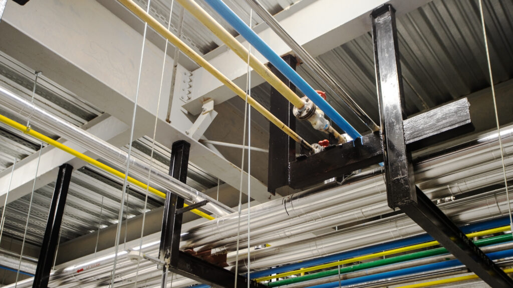
Clash detection is comparing models and flagging conflicts. Three types are important:
- Hard clashes: two objects occupy the same space, e.g., a duct running through a beam.
- Soft or clearance clashes: objects do not touch but leave no room for insulation, hangers, maintenance, or access.
- Workflow or sequence clashes: the install order is incompatible, like a big vessel that cannot get in once the wall closes.
Where Pharma Models Clash Most
- The ceiling void where supply ducts, HEPA housings, return risers, sprinklers, cable trays, and process pipes all compete
- Hygienic piping for water for injection, clean-steam condensate and CIP/SIP circuits, where specified slopes and drainability requirements must be coordinated with ducts, structure and other services
- Penetrations in the walls and floors of the cleanroom envelope that must preserve cleanability and room-envelope integrity while supporting the pressure-control strategy
- Point-of-use drops and equipment connection points that must conform to approved vendor drawings
- Routine access to service filters, dampers, and valves
How to Run a Clash Process That Works
- Approve model rules and clash tolerances in the BIM execution plan
- Have each discipline put out models on a regular cadence.
- Run automated tests by pair, e.g., HVAC vs. process piping.
- Filter the noise and assign every real clash an owner and a due date.
- Prioritize field-relevant clashes, not model noise.
- Run the tests again after each coordination cycle and verify closure of assigned issues.
The aim is not simply to get every red dot cleared. A small geometric clearance may still create a problem for insulation, supports, installation or maintenance access. Clearance rules therefore need to consider constructability and operation, not just physical intersection.
Level of Development: How Much Detail Each Stage Needs
The Level of Development (LOD) indicates the maturity of a model element. Based on previous work by AIA, the BIMForum specification begins at LOD 100 and goes to LOD 500:
- LOD 100: Conceptual
- LOD 300: Specific geometry, including size, shape, location, quantity, and orientation to a defined accuracy.
- LOD 350: Geometry developed sufficiently to support coordination with interfaces to other building systems.
- LOD 400: Fabrication, assembly and installation information.
- LOD 500: Represents an existing or as-constructed condition established through observation, field verification or interpolation, with the required accuracy stated separately. LOD 500 should not be interpreted as a higher development level than LOD 400.
ISO 19650 addresses information management throughout the asset lifecycle, while ISO 7817-1:2024 establishes concepts and principles for specifying the level of information need. This approach should not be treated as equivalent to the LOD 100 to 500 scale. Define the information needed for each stage; the project requirements determine what has to be delivered.
A simple rule is effective. Set the level of decision required for the element. Concept work requires zones, grades, and flows. Design development requires main routes and equipment envelopes near LOD 300. Elements requiring construction-level coordination may progress toward LOD 350, while fabrication-ready modules, spool pieces and supports may progress toward LOD 400 depending on project requirements. Starting every element at LOD 400 from day one can create unnecessary modelling effort. Conversely, modelling an air handler as a plain box for too long can hide real coordination risks.
Read More: Single Use vs Stainless Steel Bioprocessing
Equipment Clearances, Constructability, and Procurement Coordination
Equipment Clearances
Include keep-out volumes in the model for door swings, removal paths, pull space, filter changes and cleaning access. Clash tests then identify any element that encroaches. Check the biggest equipment first. If the freeze dryer or autoclave can enter but cannot later be removed, the constraint may only become apparent when major maintenance or replacement is required.
Constructability
Connect the model to the schedule with 4D sequencing. It tells you what equipment has to be in place before walls close, which services need to be installed first in congested overhead zones, and where rigging paths run. Temporary openings in the model should be planned so they do not surprise the cleanroom contractor.
Procurement Coordination
Long-lead items such as air handlers, isolators, autoclaves and water skids may have dimensions, weights and connection points that continue to develop through vendor selection and detailed engineering. Load vendor data to the model as it arrives. When a vendor modifies a drawing, update the model and perform the clash tests again. Keep a log linking every item purchased to its model status, ensuring that procurement commitments are based on an adequately mature and approved design basis and that approved vendor information is incorporated back into the coordinated model.
As-Built Information: Close the Gap Between Drawings and Site
Even the best planned project changes on site. Pipes are moving. Supports change. Field decisions never make it to the drawings unless someone catches them.
Log field change as they happen. Reality capture techniques such as laser scanning provide verification of the model against the built condition. The model and related drawings should be progressively updated as commissioning and qualification activities proceed and should reflect the controlled as-built condition at final handover. Current C&Q practice also recognizes that field conditions can differ from design documents and that commissioning records need to reflect the actual installed system. The model should therefore remain aligned with the controlled as-built condition.
From Model to CQV
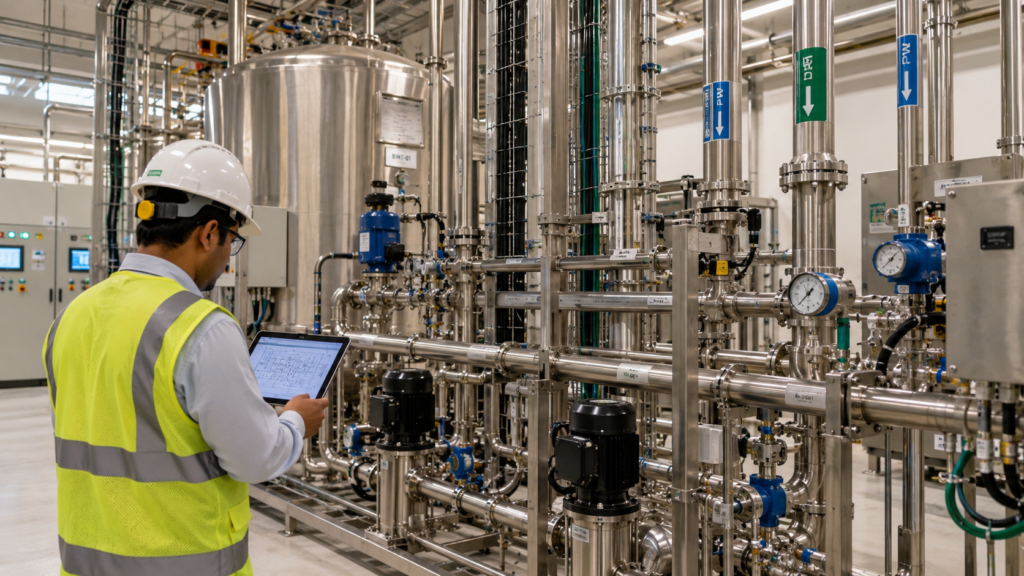
The qualification world has increasingly moved toward engineering-driven, science- and risk-based verification. ASTM E2500-25, updated in 2025, describes a lifecycle approach covering specification, design, verification and qualification of pharmaceutical and biopharmaceutical manufacturing systems. The revision gives Design Qualification a clearer role and further aligns verification with current quality risk management principles. It also clarifies the relationship between Good Engineering Practice commissioning documentation and the appropriate level of Quality Unit oversight.
A well-kept model supports that approach in several ways:
- Evidence of design review: clash log and clearance checks show what the team reviewed and fixed.
- Installation checks: Walkdowns compare the built system to a tagged model.
- Fewer transcription errors: Equipment and instrument tags can transfer structured data from the model into associated records.
- Airflow and pressure logic: The HVAC model shows the pressure cascade design that qualification tests later verify
Digital twins can extend the same digital approach into design verification and operations. A pharmaceutical manufacturing digital twin team can take BIM models, HVAC specs, personnel flow, and fluid dynamics simulations and put them into a twin to stress test the design before construction. Industry applications have reported reductions in commissioning effort, rework and root-cause investigation time, but the scale of benefit depends on model maturity, data quality and the specific use case.
These outcomes should therefore be treated as project-specific rather than guaranteed benchmarks. The twin also has to be checked against data from the physical facility, and its value is in supporting design review, investigation and operational insight, not in replacing IQ, OQ, or PQ.
Lifecycle Asset Management After Handover
Handover is where many models die. The facility keeps changing, the model freezes, the team disbands, and the project ends.
Structured asset data keeps the model up to date. COBie is one example of a common format for the transfer of facility management information between the design and construction teams and the owner. The asset information model then supports maintenance planning, calibration schedules, and future change projects.
The BIM model should therefore be treated as a living information asset under controlled change management rather than a static output of the capital project. This is especially important for CDMO and modular sites, which often change equipment and product mixes.
Where MES and QMS in Pharma Fit
Two links strongly influence whether a model remains useful after handover:
- Quality management system (QMS): Link GxP-relevant model updates to change control. Changes affecting critical aspects or critical design elements may require GMP change management, while other engineering changes may remain within controlled engineering change management, depending on their impact and risk.
- Manufacturing execution system (MES) and building controls: determine early what data the twin reads. A read-only data connection can be a sensible starting point. Then verify the model outputs against field data before using the twin to support operational decisions.
Plan these data and change-control interfaces early to avoid costly integration or model-rebuilding work after go-live.
Next Steps: Set Up Your Model in Order
- Define information requirements for design, CQV, and operations.
- Develop a BIM execution plan according to LOD or information requirements by stage.
- Before the first clash test, define clearance and keep-out rules.
- Link the procurement register and vendor data to the model.
- Plan your as-built capture method before construction begins.
- Link design review, installation verification, and qualification records to appropriate model outputs.
- Link the model to change control and figure out what a twin will read.
Pharma Access capabilities span engineering design, procurement and supplies, construction and installation, and project management. That spread of phases shows why maintaining a coordinated information model from the first design stages through handover can help reduce interfaces, rework and information loss.
Frequently Asked Questions
What is BIM in pharma construction?
It’s a 3D integrated model that also has data on all systems from rooms and ducts to pipes and equipment. Teams use it to design, clash check, plan construction, and hand over structured asset information to operations.
What is the difference between BIM and a digital twin?
BIM represents the facility as it is designed and constructed at a point in time. A digital twin is connected to the physical facility or system through operational data and can reflect changes in its condition or performance.The twin often begins with geometry and asset data from BIM.
How does clash detection help a pharma project?
It flags conflicts between disciplines, like ducts against sloped process piping, before anyone builds them. It also identifies clearance conflicts affecting insulation, installation, maintenance and equipment removal. It’s much cheaper to fix a clash in the model than on site.
Which LOD should a pharma project use?
Link the decision to the level. Low-detail concept work. LOD 300 is often used for design coordination. Elements requiring construction-level coordination may progress to LOD 350, while fabrication-ready elements may progress to LOD 400 depending on the project requirements. LOD 500 represents verified existing or as-constructed conditions rather than simply a higher level of model development. ISO 7817-1 projects can instead define the required level of information needed for each information exchange.
Does a digital twin replace IQ, OQ, and PQ?
No.” The twin helps with early detection of design flaws and helps in investigations but does not replace qualification. Teams must verify the twin, its data and its assumptions against the physical facility to a level appropriate to its intended use before relying on it for operational or GxP-relevant decisions.