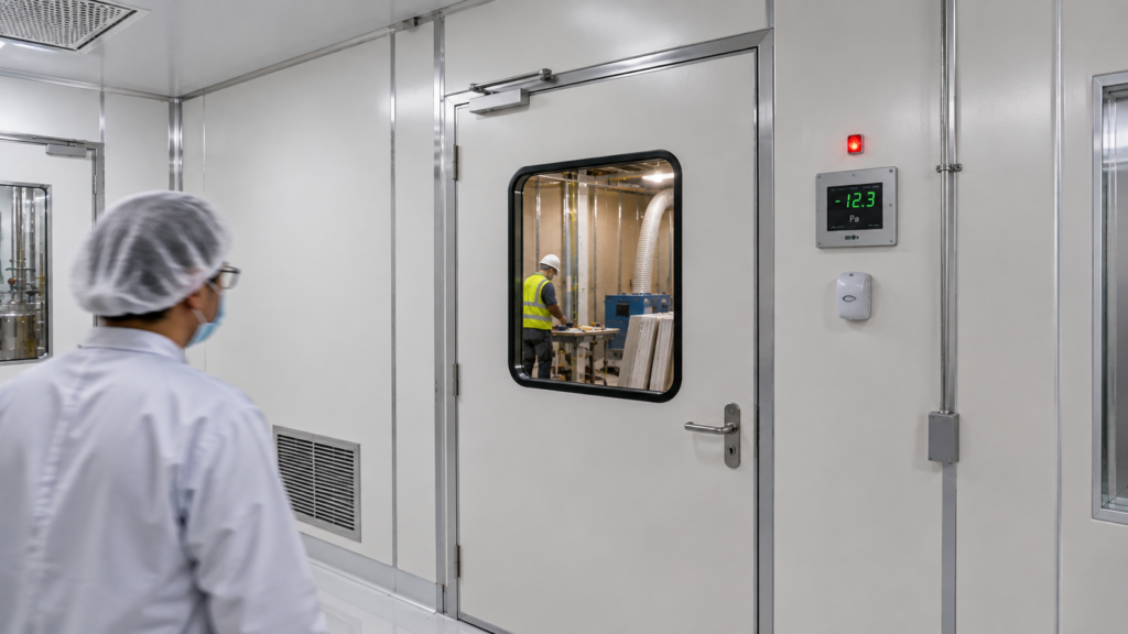
IQ, OQ and PQ in Pharma: A Practical Facility & Equipment Qualification Guide

IQ, OQ and PQ in Pharma

If you work anywhere near a pharma manufacturing floor, you have heard these three letters thrown around constantly: IQ, OQ, PQ. They sound like alphabet soup until you actually need to install a new tablet press or bring a filling line online, and suddenly they are the only thing standing between your equipment and production. No one involved in facility projects can afford not to understand IQ, OQ, and PQ pharmaceutical industry requirements. That’s the core of how manufacturers demonstrate that equipment, facilities, utilities and systems are suitable for their intended use and regulators assess the documented evidence supporting that qualification.

This post goes through what each stage covers, how they work together, and what real IQ, OQ, and PQ HVAC pharmaceutical industry work looks like on the ground. We’ll try to keep it simple and avoid dense regulatory language where possible.

What Do IQ, OQ, and PQ Actually Mean?

Qualification is the documented process that verifies that equipment, systems, or utilities are fit for their intended use. It provides documented evidence that the equipment or system is ready to perform its intended function, not just sitting in the room looking good.

The three core stages are as follows:

  • Installation Qualification (IQ): Verifies that the equipment is installed properly, utilities are connected correctly, and all documentation and components agree with the approved engineering drawings and specifications.
  • Operational Qualification (OQ): Tests machine functions like speed, temperature, alarms, interlocks, and control systems to confirm proper operation within defined limits.
  • Performance Qualification (PQ): Demonstrates that the facility, utility, equipment, or system performs effectively and reproducibly under representative normal operating conditions.

Each step builds on the one before. You can’t skip IQ and go right to OQ, because testing how a machine works isn’t meaningful if it was never verified to be installed properly in the first place. Depending on equipment complexity and the approved qualification strategy, however, IQ and OQ may be performed as a combined IOQ.

DQ: The Step Before IQ

All this happens after most facilities have been through a Design Qualification (DQ) stage.DQ itself is normally preceded by a User Requirements Specification (URS), which defines what the facility, utility, equipment, or system is expected to achieve. DQ makes sure the equipment or system is designed to meet GMP and user requirements before you buy it or before the design is finalised. . For instance, before buying a tablet compression machine, a facility will confirm that the design matches the intended production speed, batch size, and cleaning needs. Getting DQ right early reduces downstream redesign and qualification rework. Catching a design mismatch on paper is much cheaper than catching it after the equipment is already installed.European Commission Qualification and Validation.

DQ IQ OQ PQ Equipment Qualification in Pharma: The Full Sequence

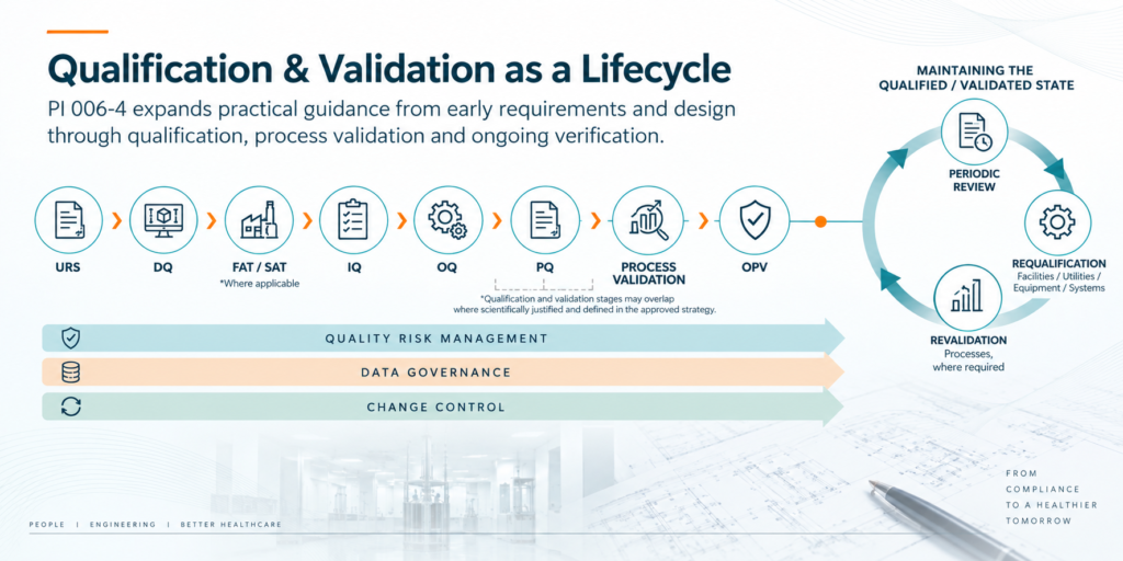
The full sequence for DQ, IQ, OQ, and PQ equipment qualification that pharma teams follow typically progresses from URS and DQ through FAT/SAT, where applicable, followed by IQ, OQ, and PQ. Each stage is logically connected and should be appropriately documented before progression, although stages may be combined or conditional progression may be authorised where scientifically justified and documented.

Installation Qualification (IQ) is the first step. It confirms that:
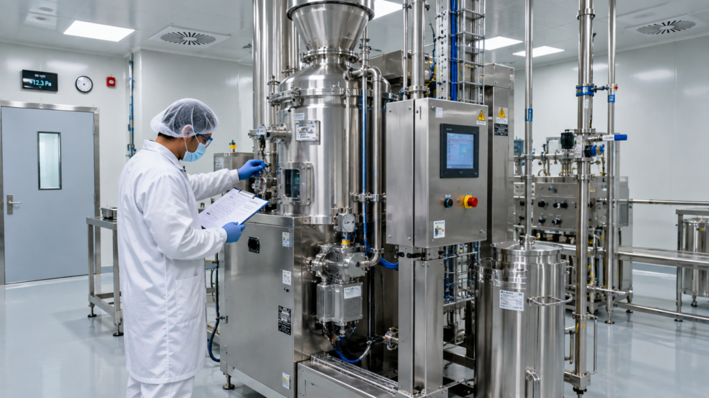
Installation Qualification (IQ) is the first step. It confirms that:
  • The equipment conforms to approved engineering drawings and specifications, purchase requirements, and vendor specifications.
  • Utilities: power, water, and compressed air are connected correctly.
  • All manuals, drawings, and calibration certificates are available and correct.
  • The equipment is physically situated in an environment which satisfies its intended operating conditions.
  • If careful documentation is skipped here, problems may not show up until much later, particularly when records are requested during review or inspection.

Operational Qualification (OQ): OQ tests the actual functions of the equipment. In this stage, it checks things like:
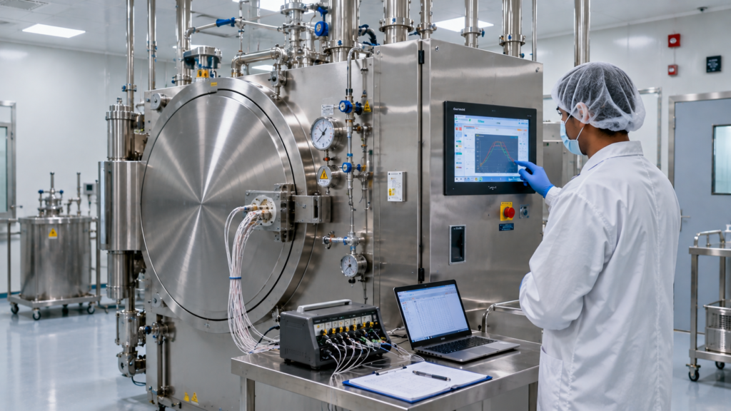
Operational Qualification (OQ)
  • Speed and timing controls are within their specified ranges.
  • Alarms will fire correctly when conditions are out of range.
  • Interlocks and safety systems operate as intended.
  • Control systems maintain set points under varying loads.
  • Relevant upper and lower operating limits and worst-case conditions are challenged where appropriate. 

A lot of real problems get caught at OQ. A machine could be installed perfectly but still not hold temperature within spec, or its alarm could activate outside the specified set point or tolerance. The whole point of the exercise is to find that during OQ, not during a live production run.

Performance Qualification (PQ)
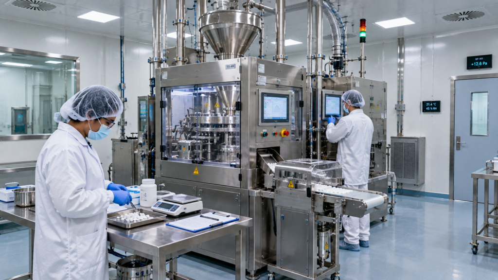
Performance Qualification (PQ)

It is the last step and should normally begin when IQ and OQ are both complete. Through PQ, a facility demonstrates with real evidence that its equipment or system performs effectively and reproducibly under representative normal operating conditions and across the intended operating range. For example, a PQ for a tablet press may involve production of full-scale batches or representative production runs, with justified sampling used to evaluate relevant equipment-performance, in-process and product-quality parameters, as applicable.

PQ should not be confused with Process Performance Qualification (PPQ). Equipment PQ demonstrates that a facility, utility, equipment item or system performs as intended under representative operating conditions. PPQ is part of process validation and evaluates whether the commercial manufacturing process, using qualified facilities, utilities and equipment together with trained personnel and established controls, can reproducibly manufacture products meeting its predetermined quality requirements.

IQ OQ PQ Examples: What This Looks Like in Practice

Reading about IQ, OQ and PQ in the abstract is only so helpful. Here are a few concrete IQ OQ PQ examples that illustrate how this plays out for common pharma equipment:

  1. Autoclave: IQ verifies correct installation and utility connections. OQ tests include cycle controls, temperature distribution, pressure control, alarms and interlocks. PQ confirms reproducible cycle performance and heat penetration across defined load configurations, with appropriate biological challenge where applicable.
  2. HVAC system: IQ verifies ductwork, filters, instrumentation and controls installed to specification. OQ checks airflow rates, pressure differentials, environmental controls and alarm response. PQ verifies that the system maintains the required environmental conditions and cleanroom performance under representative operating conditions, as applicable.
  3. Filling line: IQ confirms mechanical installation and utility hookups. OQ tests fill accuracy, speed settings, alarms, interlocks and reject mechanisms across the intended operating range. PQ confirms that under representative production conditions, the line performs consistently over an appropriate operating period, including personnel changes and routine operating interventions where relevant.
  4. Stability chamber: IQ verifies installation and calibration records. OQ verifies temperature and humidity control over the defined operating range. PQ confirms the chamber holds these conditions reliably over an extended period with an appropriate representative load.

Every piece of GMP-impacting pharma equipment gets this same basic treatment, with the scope and depth of qualification scaled according to its risk, complexity, criticality and intended use.

Facility Qualification vs Equipment Qualification

There is a distinction that trips up a lot of people new to this subject, and it’s worth being clear about. Qualification of equipment is specific to individual machines, such as a tablet press or an autoclave. Facility qualification is broader, covering GMP-relevant facilities and supporting systems that support all that equipment together, things like HVAC, water systems, clean utilities, and the overall cleanroom environment.

A successful programme in this area confirms that the building itself, not just the individual pieces of equipment inside, meets the conditions needed for GMP manufacturing. Both approaches have the same DQ, IQ, OQ, and PQ logic, but qualifying the whole building usually takes more time and involves more interconnected systems, as a change in one utility can impact several rooms and processes at the same time.

Why IQ, OQ, and PQ in the Pharmaceutical Industry Matter So Much

Without documented evidence across DQ, IQ, OQ, and PQ, regulators cannot verify that your equipment and facility consistently support GMP manufacturing. This is not a paperwork formality. A pharmaceutical product made using inadequately qualified GMP-critical equipment or systems may introduce real risks for patients, whether it’s inconsistent dosing, contamination, or inadequate control of a sterilisation process. 

Regulatory bodies, including the FDA, consider qualification as one of the key activities that must be completed before equipment and utilities are used for commercial-scale Process Performance Qualification and before routine commercial distribution begins.

Common Mistakes Facilities Make With IQ, OQ, and PQ

During qualification work, a handful of recurring issues show up again and again:

  • You start OQ before IQ is adequately completed or formally released, without a documented combined IOQ or conditional-progression strategy, forcing teams to retest functions once installation gaps are identified late.
  • Weak or absent DQ documentation, meaning there is no clear baseline against which equipment can be tested during later stages.
  • Treating PQ as a formality rather than a genuine test under realistic production loads and shift patterns.
  • Bad change control, where a mid-project equipment substitution or design tweak never makes it back into the qualification protocols.
  • Disconnected facility and equipment qualification, where HVAC or utility qualification is on a separate track from equipment qualification, creating gaps at the interfaces between them.

Where This Fits Into the Bigger Picture: Commissioning Qualification Validation

IQ, OQ and PQ do not happen in isolation. They sit within the broader commissioning qualification validation framework that governs how a pharma facility is built and brought online. Commissioning provides engineering evidence that systems have been installed, tested and operated in accordance with approved design requirements and design intent. Qualification (DQ, IQ, OQ, and PQ) provides the documented GMP evidence that applicable facilities, utilities, equipment and systems are suitable for their intended purpose. Validation demonstrates that the manufacturing process can consistently deliver product meeting predetermined quality requirements.

Seeing these as one connected lifecycle (rather than three separate handoffs between different teams) is what prevents a facility from finding out about gaps after production has already begun.General Principles and Practices, Guidance for Industry

How This Connects to Facility Design and Construction

Qualification results are determined well in advance of anyone executing a single IQ protocol. The design and construction of a facility will determine the ease with which qualification proceeds. For a more detailed look at how design and construction decisions flow into qualification, our guide to facility design & construction spans the full lifecycle from concept through commissioning and pairs well with the qualification concepts covered here.

Our teams at Pharma Access take design intent through construction and into CQV, so validation protocols are written against decisions made by our own engineers, not recreated after the fact from someone else’s drawings. A big part of that continuity is why DQ, IQ, OQ, and PQ equipment qualification pharma work can maintain clearer traceability from design intent through commissioning and qualification while reducing the risk of late-stage documentation and system-interface gaps. You can read more about our approach on the Pharma Access about page.

Getting IQ, OQ, and PQ Right the First Time

Facilities that treat design and construction decisions, the kind covered in our guide to facility design & construction, as part of the qualification story from day one tend to move through IQ, OQ and PQ with far fewer surprises. 

A handful of habits distinguish teams that do well in qualification from those that get stuck:

  1. Write the URS and DQ documentation before finalising equipment procurement so that IQ has a clear approved specification to test against.
  2. Instead of running stages in parallel without a justified qualification strategy, close out each stage or formally authorise progression before starting the next one.
  3. Build realistic PQ scenarios covering an appropriate operating period and representative conditions, including adjustments, stoppages, personnel changes and material replenishment where relevant, not just a single best-case run.
  4. Keep facility and equipment qualification linked, so utility and HVAC qualification corresponds to the equipment schedules that depend on them.
  5. Maintain tight change control throughout the project so that any equipment or design change is reflected immediately in the qualification protocols and associated documentation.

Wrapping Up

Good IQ OQ PQ pharmaceutical industry practice is not a bureaucratic hoop to jump through in manufacturing. They are the structured trail of evidence that proves that your equipment and facility actually do what they were designed to do, consistently and safely. Get the sequence right, document thoroughly, and treat facility and equipment qualification as one connected process, and your project is better positioned for inspection readiness while reducing the risk of qualification-related rework.

FAQs

What is the difference between IQ, OQ, and PQ? 

IQ verifies the equipment is installed correctly. OQ tests that it runs within defined limits. PQ confirms that the equipment or system performs effectively and reproducibly under representative operating conditions. The stages normally progress logically, although qualification activities may be combined or progression may be conditionally authorised where appropriately justified and documented.

What does DQ mean, and why does it come before IQ? 

DQ is Design Qualification. It ensures the equipment’s design conforms to GMP and the approved URS before procurement or design finalisation, providing IQ with a clear specification to check installation against later.

Can any of these qualification stages be skipped for simple equipment? 

The rigour can scale with risk, but qualification activities may be combined or simplified where justified by risk, complexity and criticality. What should not be omitted for GMP-impacting equipment is adequate documented evidence that the equipment is suitable for its intended use.

What is the difference between equipment qualification and facility qualification? 

Equipment qualification is done on a per-machine basis. The qualification of the facility is the qualification of the broader building systems, such as HVAC and utilities, that support all the equipment as a whole. They both follow the same DQ, IQ, OQ, and PQ approach, just at a different scale.

How long does IQ OQ PQ typically take for a new facility? 

There is no universal duration for IQ, OQ and PQ on a new pharmaceutical facility. The timeline depends on facility size, the number and complexity of systems, equipment criticality, FAT/SAT strategy, documentation readiness, qualification sequencing, deviations and the overall CQV execution plan.
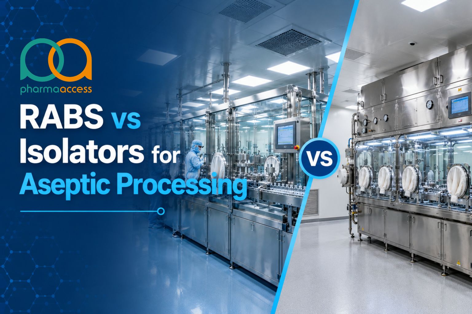
RABS vs Isolators for Aseptic Processing: Design, Annex 1 & Qualification Compared

RABS vs Isolators for Aseptic Processing

If your facility fills sterile products, you’ve likely been faced with this decision at some point: RABS vs isolators. Both systems are designed to reduce contamination risks associated with personnel and direct human intervention during filling, but they get there in very different ways – and that difference shows up in your design and construction cost, your cleanroom grading, and how your facility gets qualified.

This post explains how the two technologies differ, what the current EU regulatory guidance requires of each, and what qualification looks like once the system is installed. We won’t dive deep into the engineering details; we’ll keep it simple.

What Are RABS and Isolators, in Plain Terms?

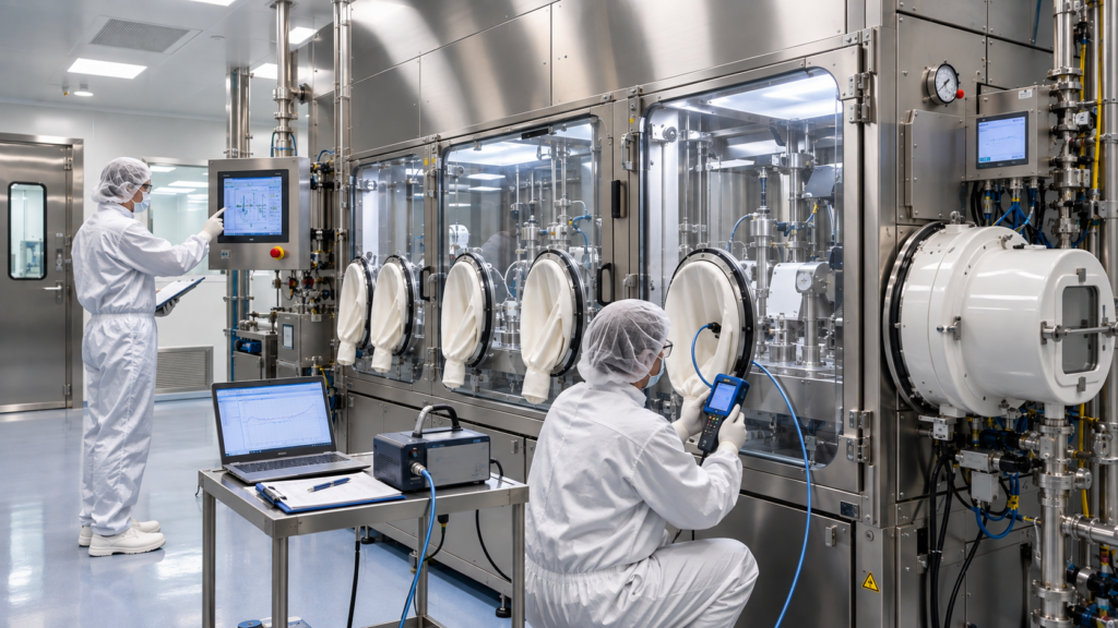
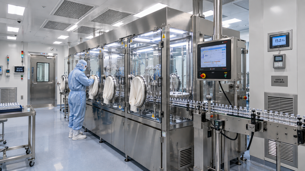
An RABS, or Restricted Access Barrier System, is effectively a physical barrier made around a filling line, with gloved ports through which operators can reach when needed. In normal production, the barrier is closed, but depending on the design, doors are rarely opened and only under strictly predefined conditions. It provides an enclosed, but not fully sealed, environment that separates the Grade A processing zone from the surrounding cleanroom.

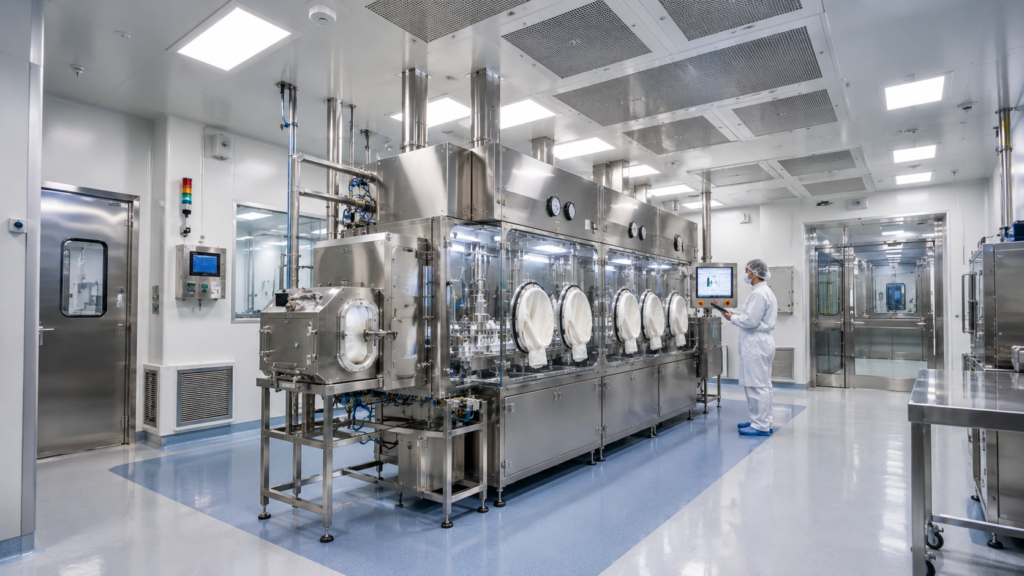
An isolator is more. It’s a self-contained, enclosed system that provides continuous isolation of its interior from the surrounding environment, with a controlled Grade A work zone and a reproducible bio-decontamination process. Operators only interact with the process through glove ports or half-suits. The isolator provides continuous separation from the surrounding cleanroom, allowing lower background cleanroom grades where justified through risk assessment and the Contamination Control Strategy (CCS).

The main difference is that RABS provides an enclosed but not fully sealed barrier between the aseptic process and the surrounding cleanroom. Isolators provide continuous isolation of the internal Grade A environment from the external environment.

How EU GMP Annex 1 Treats RABS vs Isolators

The 2022 update to this guidance changed the expectation of how regulators want manufacturers to think about barrier technology. Cleanrooms, laminar flow hoods and open processing were common enough before this revision. The revised annex places greater emphasis on appropriate barrier technologies and contamination-control measures for protecting critical aseptic processing zones.

The use of RABS and isolators in the maintenance of the required conditions and reduction of microbial contamination associated with direct human intervention in the critical zone is described as beneficial in this guidance. It states that the use of these should be considered as part of the Contamination Control Strategy (CCS) and that any alternative approach needs justification. In practice, that means a manufacturer who chooses not to use one of these systems now has to justify the decision, rather than the other way around.

EU GMP Annex 1 RABS Requirements

EU GMP Annex 1 RABS Requirements

The annexe is specific as to what a RABS installation must show. It should be maintained at Grade A conditions with unidirectional airflow and first air protection in the critical zone, and the background environment around an RABS used for aseptic processing needs to be at least Grade B. That Grade B requirement is a big part of what makes RABS more expensive to operate than it might first appear, since the entire surrounding room has to be built and maintained to that classification.

What Annex 1 Says About Isolators

Isolators are handled differently because they provide continuous isolation of the interior from the external environment. Isolators provide continuous isolation of the interior from the external environment, and the annex describes two types of isolators: closed and open. The difference between the two is the manner in which materials move in and out during operation. The background classification requirements are different from those for RABS: the surrounding room for an open isolator is generally required to be at least Grade C, and for a closed isolator at least Grade D. The final background classification should be based on risk assessment and justified within the CCS, and a higher grade may be required where additional process risks are identified. That is a much lower background classification requirement than the Grade B environment a RABS installation requires.

Comparing RABS and Isolators Side by Side

Here’s a quick summary of the main differences that matter for facility design.

  • RABS Grade: Minimum Grade B background required. Isolator background: Depending on the design, open isolators generally require a minimum Grade C background, while closed isolators require a minimum Grade D background, subject to risk assessment and CCS justification.
  • Separation level: RABS has an enclosed but not fully sealed barrier, with doors rarely opened and only under strictly predefined conditions. Isolators provide continuous isolation of the internal Grade A work zone from the external environment.
  • Air handling: RABS maintains Grade A conditions with unidirectional airflow, first air protection and positive airflow from the critical zone toward the supporting background environment. Isolators maintain Grade A conditions within the internal work zone, with airflow requirements depending on whether the isolator is open or closed and on the process design.
  • Decontamination: Isolators require an automated, validated and controlled interior bio-decontamination process using a suitable sporicidal agent. RABS require validated routine sporicidal disinfection of the interior surfaces to ensure a suitable environment for aseptic processing.
  • Cost of capital: Isolators are often more expensive to purchase up front because they are self-contained and automated. Although the initial cost of RABS might be lower, the continued operating costs of Grade B rooms could be higher.
  • Flexibility: RABS systems are often easier to retrofit into existing filling lines. Isolators can require greater integration with the filling line, transfer systems, utilities, controls and facility design, although retrofit feasibility depends on the existing installation.

    Know More : European Commission Qualification and Validation

Aseptic Barrier Systems and Qualification: What Changes

RABS and isolators are both forms of aseptic barrier systems. However, the qualification of each is slightly different, based on the way each interacts with the surrounding facility.

RABS Qualification

To be able to qualify a RABS installation, the interaction between the barrier and the Grade B room surrounding it has to be considered. This means that airflow visualisation studies have to be performed to show that unidirectional flow is maintained and to demonstrate the absence of air ingress during interventions, including door openings where applicable. Since it is easy to transfer contamination between the RABS and the surrounding Grade B space, environmental monitoring needs to be performed within the RABS and the surrounding Grade B space as defined by the facility’s environmental and process monitoring strategy.

Isolator Qualification

Isolator Qualification

The qualification of an isolator is often more concentrated on the decontamination cycle, as this is the step that establishes the validated bio-decontaminated condition inside the unit before aseptic processing. Qualification protocols usually check that the vapour-phase decontamination cycle consistently achieves its predefined and validated acceptance criteria and include leak testing to confirm the isolator maintains its integrity at defined intervals. This qualification work places relatively less emphasis on the background room performance and more on the isolator’s own containment and decontamination systems because the surrounding room requirement is lower.

Glove-system integrity is also an important part of isolator control. Annex 1 expects leak testing of isolator glove systems at defined intervals and generally at the beginning and end of each batch or campaign, with additional testing where required by the validated campaign length. 

Aseptic Process Simulations for Both Systems

With Annex 1, there are heightened expectations for aseptic process simulations across the board, no matter the barrier technology a facility uses. The updated guidance introduces a tighter action level for Grade A viable contamination, with the Grade A action limit defined as “no growth” and any growth requiring investigation. Initial qualification must be performed on RABS and isolator lines with at least three consecutive satisfactory simulations covering all working shifts in which the aseptic process may occur, followed by periodic revalidation, typically twice per year for each aseptic process, each filling line and each shift. Each operator should also participate in at least one successful APS annually.

Know More : Manufacture of Sterile Medicinal Products

Which System Should Your Facility Choose?

There is no single answer that fits all, and EU GMP Annex 1 does not establish a hierarchy that requires isolators to be selected over RABS. The appropriate barrier technology should instead be justified through the CCS and quality-risk-management approach.  But the practical answer tends to boil down to a few things:

  • New construction or retrofit? RABS can generally be added to an existing filling line with less extensive facility integration in some applications, although the feasibility depends on the existing line and cleanroom design.
  • What is the risk level of your product? Processes involving complex or frequent interventions, challenging aseptic transfers or other elevated contamination risks may benefit from the greater degree of separation provided by isolator technology. However, product modality alone should not determine the barrier-system selection.
  • What is the operational maturity of your team? The decontamination cycle and integrity of the gloves require more detailed management, and the training of the staff and procedures must be in line with this level of detail.
  • What does your budget and schedule allow? Isolators tend to be more expensive initially, but they can reduce the ongoing costs of maintaining a Grade B environment.

For existing facilities, a phased barrier-technology strategy may be considered, with RABS retained or implemented where technically appropriate and isolator technology evaluated for new lines or major expansions based on the process and facility requirements.

Designing Your Facility Around the Right Barrier Choice

Designing Your Facility Around the Right Barrier Choice

The decision to employ RABS or isolators is never isolated. It drives HVAC sizing, room classification, growing requirements, and even the square footage the aseptic suite needs.It can also influence material-transfer strategy, intervention design, environmental monitoring, decontamination systems and the overall CQV scope. Getting this decision right at the concept design stage saves the costly rework that comes from discovering mid-construction that the room was built for the wrong background grade.

At Pharma Access, our engineering design and CQV teams partner with clients through this decision from the earliest planning stage, considering product risk, facility layout, and long-term operational plans before committing to an isolator- or RABS-based approach. We make that decision and take it through cleanroom design, HVAC, and qualification as one connected process so the facility that’s built is aligned with the aseptic process it needs to support. Read more about our approach on the Pharma Access about page.

Wrapping Up

Both RABS and isolators are there to solve the same underlying problem, which is keeping people away from sterile products during filling. RABS can offer lower initial barrier-equipment cost and greater retrofit flexibility in suitable applications but still requires a Grade B background and careful qualification of the barrier system and its interaction with the surrounding environment. 

Isolators provide continuous separation, lower background grade requirements, and qualification that is focused strongly on barrier integrity and validated bio-decontamination performance. Annex 1 makes clear that RABS or isolators should be considered as part of the CCS, while alternative approaches need to be justified.

FAQs

What is the main difference between RABS and isolators? 

RABS is an enclosed but not fully sealed barrier system whose doors are rarely opened and only under strictly predefined conditions, and usually needs a Grade B background room. Isolators are enclosed systems providing continuous isolation of their internal Grade A work zone from the surrounding environment and can often operate in a Grade C or D environment depending on whether the isolator is open or closed and on the CCS risk assessment.

Does EU GMP Annex 1 require isolators over RABS? 

Not exactly. Annex 1 states that RABS or isolators should be considered in the Contamination Control Strategy, with justification for alternatives. It does not establish isolators as a regulatory requirement over RABS; the selection should be based on process risk, barrier design and the CCS.

Why do isolators need a lower background cleanroom grade than RABS? 

Isolators provide continuous isolation of their internal Grade A environment from the surrounding cleanroom, and so lower background grades can be justified based on the isolator design and risk assessment. RABS are enclosed but not fully sealed, so Annex 1 requires a minimum Grade B background for RABS used for aseptic processing.

What does isolator qualification focus on that RABS qualification does not? 

Isolator qualification is very focused on the decontamination cycle, checking that the validated bio-decontamination process consistently operates within its defined cycle parameters and achieves established acceptance criteria, together with isolator and glove-system integrity testing. RABS qualification is more about maintaining Grade A conditions, airflow performance and demonstrating the absence of air ingress during interventions, including door openings where applicable, together with the required Grade B background.

Can an existing RABS line be converted to an isolator later? 

It can be done, but typically at a cost, as isolators may require significant integration with the existing filling line, transfer systems, HVAC, utilities, automation and room configuration. Many facilities therefore evaluate isolator retrofit feasibility against installing the technology as part of a new line or major expansion.

PIC/S PI 006-4: What the 2026 Qualification & Validation Update Means for CQV

PIC/S PI 006-4: What the 2026 Qualification & Validation Update Means for CQV

Pharma teams that have been running qualification and validation programmes under the same PIC/S recommendations for years are about to see a significant change in the guidance supporting Annex 15. PIC/S has made a major revision to its Recommendations on Qualification and Validation, PI 006-4, and it comes into effect on 1 October 2026. If your facility is preparing for PIC/S qualification and validation expectations in 2026, be it a new build, an expansion, or an upgrade to an existing plant, this document changes the level of practical guidance available to inspectors and industry.

This post will cover what actually changed with the PIC/S qualification and validation 2026 requirements, why it matters to your CQV programme, and what steps to take before the effective date. We’ll keep it practical and avoid dense regulatory language where possible.

What Is PIC/S Annex 15, and What Just Changed?

Annex 15 is the annex to the PIC/S and EU GMP Guide that sets out the basic principles of qualification and validation in pharmaceutical manufacture. Since its last major revision in 2015, it has remained relatively unchanged. Alongside Annex 15, there is a separate and more detailed recommendations document for inspectors and industry, PI 006. This document provides additional practical guidance in areas where PIC/S identified the need for more detail than Annex 15 provides.

That’s what just changed: that supporting recommendations document. PIC/S has approved a new version, PI 006-4, which supersedes PI 006-3 dated 25 September 2007. The new version takes effect on October 1, 2026, and is a substantial rewrite of the recommendations after nearly 20 years.

Meet PI 006-4: The New Recommendations Document

PI 006-4 is officially entitled PIC/S Recommendations on Qualification and Validation. It’s hard to see why the change is so important, unless you know what it’s replacing. The old PI 006-3 was one document containing individual recommendations covering the Validation Master Plan, installation and operational qualification, non-sterile process validation, and cleaning validation.

PI 006-4 substantially reorganises and expands that material within one updated document. It builds on the 2015 revision of Annex 15. It incorporates quality risk management principles throughout the qualification and validation lifecycle, rather than treating risk assessment as a separate add-on step.

PI 006-4 Significant Additions:

PI 006-4 Significant Additions

Some additions are notable for covering ground the old guidance barely touched:

  • Prequalification stages including the User Requirements Specification (URS), Design Qualification (DQ), Factory Acceptance Testing (FAT) and Site Acceptance Testing (SAT), giving teams more detailed guidance on the planning and verification work that happens before formal IQ, OQ and PQ.
  • Performance qualification in more detail than the older documents provided.
  • Ongoing (or Continued) Process Verification (OPV), extending process monitoring beyond initial validation and across the commercial product lifecycle.
  • Continuous Process Verification (CPV), which PI 006-4 addresses as an alternative approach to initial process validation where appropriate process understanding and control support its use.
  • Transport verification, a gap many facilities have previously filled in an ad hoc way.
  • Packaging validation now has its own dedicated coverage, specifically for solid dose products.
  • Utility qualification, providing more detailed expectations for supporting utilities such as pharmaceutical water, HVAC and process gases.
  • Validation of test methods, with high-level guidance on method validation and verification rather than detailed analytical-method-validation requirements.

The principles in the document apply to the manufacture of active pharmaceutical ingredients, intermediates and finished dosage forms.

Other PI 006-4 Areas CQV Teams Should Not Overlook 

PI 006-4 also places explicit emphasis on data governance throughout qualification and validation and requires data-integrity considerations to be addressed within qualification and validation activities. It includes dedicated coverage of requalification and states that retrospective validation is no longer considered an acceptable approach to process validation. The document also clarifies that validation of GMP-impacting computerised systems remains covered by PIC/S GMP Annex 11 rather than PI 006-4 itself.

Why This Matters for Qualification and Validation Pharma Teams

It is worth clarifying what PI 006-4 is and isn’t. PIC/S refers to it as a guidance and training resource for GMP inspectors and the pharmaceutical industry, rather than the Annex 15 GMP text itself. Annex 15 continues to set out the underlying GMP principles for qualification and validation, while PI 006-4 provides additional practical guidance on how those principles can be applied.

That difference does matter in the field. Just because a facility has validation documentation doesn’t mean that it still stands up to current expectations. The underlying Annex 15 text has not been revised through PI 006-4, but PI 006-4 places much more explicit emphasis on areas such as documented ongoing process verification, supporting utility qualification, data governance and lifecycle control.

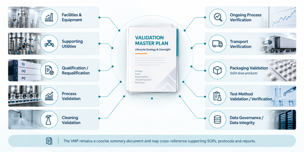
What This Means for Your Validation Master Plan

What This Means for Your Validation Master Plan

At the centre of the expanded scope of PI 006-4 is the validation master plan. The older guidance combined VMP requirements with installation and operational qualification without its recommendation, and many facilities perceived this master plan as a static document written once and visited only occasionally.

With the new guidance, this master plan should reflect the full lifecycle perspective that PI 006-4 brings, including qualification, requalification, process validation, ongoing process verification and revalidation activities. Thus, facilities will have to re-examine and revise their VMP to ensure that applicable supporting utilities, qualification and validation activities, requalification requirements and ongoing process verification are appropriately identified or cross-referenced rather than unnecessarily duplicated within the VMP itself.

Importantly, PI 006-4 describes the VMP as a summary document that should remain brief, concise and clear and may refer to existing policies, SOPs, validation protocols and reports.

Impact on Pharma Facility Qualification Timelines

Expanded qualification and validation expectations usually mean additional review and documentation, and documentation takes time to build and review. Facilities planning a pharma facility qualification programme with a completion date around or beyond October 2026 should plan for the additional scope now rather than waiting until an inspection highlights a gap.

This is particularly important for ongoing projects. Facilities that are in the middle of IQ and OQ activities developed against the older recommendations may need to revisit their CQV strategy and protocols to confirm traceability back to the URS and DQ and to ensure supporting-utility qualification is adequately addressed. The approach to ongoing process verification should then be established following initial process validation as part of lifecycle control.

Brownfield Pharma Upgrades Under the New Guidance

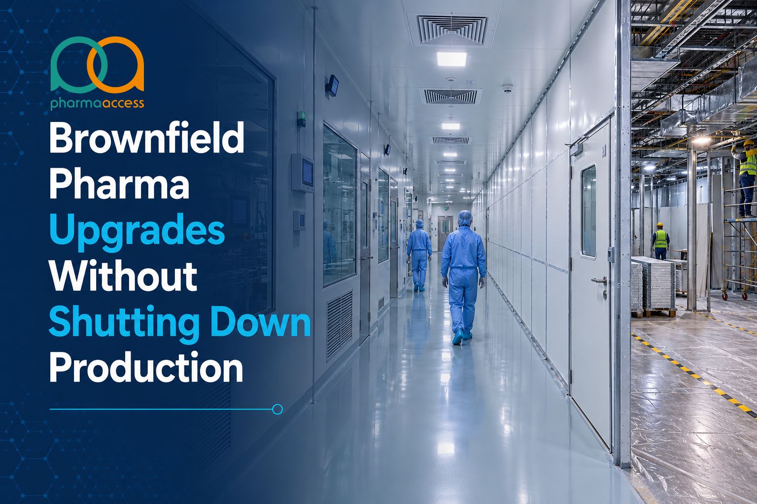
There’s a particular wrinkle with this transition for brownfield pharma upgrades. This type of upgrade must reconcile existing qualification and validation status with new expectations, all while production often continues in adjacent areas of the facility, unlike a greenfield project starting with a blank master plan.

Brownfield projects usually have more live interfaces and overlapping disciplines than a similar greenfield build. The plan needs to address the existing structure, ongoing operations, and changed validation and qualification expectations at the same time. 

PI 006-4 specifically calls for qualification and validation planning to consider risks to adjacent or connected operations, as well as risks associated with shared facilities, shared equipment, shared utilities and common HVAC systems. These considerations are particularly relevant to brownfield projects where qualification work may occur alongside ongoing GMP operations. 

Once a facility starts to map its brownfield upgrade against the expanded utility qualification and ongoing verification expectations of PI 006-4, common challenges include ageing HVAC systems, limited utility capacity, and gaps in existing qualification documentation. A team that has done this kind of transition before knows where to look for these gaps early, rather than during an inspection.

Know More : Pharmaceutical Inspection Co-operation Scheme

Steps to Prepare Before the October 2026 Deadline

Here is a practical sequence facilities can use to prepare:

  1. Re-evaluate your current master plan: Map where it already covers qualification, requalification, ongoing process verification, supporting utilities and other applicable PI 006-4 activities, and where there are gaps.
  2. Review existing qualification processes: If you have any projects not yet complete, check that IQ, OQ and PQ activities remain appropriately linked to the URS and DQ and reflect the applicable recommendations in PI 006-4.
  3. Review utility qualification documents: Expectations for supporting utilities such as HVAC, pharmaceutical water and process gases are now addressed in greater detail, so make sure your qualification strategy and records are aligned.
  4. Assess Packaging and Transport Verification Gaps: These are areas now given dedicated coverage in PI 006-4, with the packaging-validation section specifically addressing solid dose products.
  5. Review validation and verification records for test methods: PI 006-4 provides high-level expectations for these activities while recognising that detailed analytical-method-validation guidance exists elsewhere.
  6. Train quality and validation personnel on PI 006-4: Your team should be familiar with the structure and terminology of the document and understand how its recommendations supplement Annex 15.

Why Work with Experienced CQV Services

Managing this transition internally is possible, but it requires coordinated review across quality, validation, engineering and operations. Experienced CQV services can help translate regulatory updates such as PI 006-4 into practical changes to strategies, protocols and qualification activities rather than treating the update simply as a documentation exercise.This is just as important for pharmaceutical CQV work on a new facility as it is for a mid-project upgrade trying to align with the updated recommendations before project completion.

At Pharma Access, our CQV team is involved in greenfield builds, brownfield upgrades, and ongoing qualification projects, covering the entire spectrum from master plan development to IQ, OQ, and PQ execution. Since our engineering and CQV teams begin with the same design intent, validation protocols remain tied to the actual reasoning behind facility decisions, rather than being retrofitted later. 

Wrapping Up

Although PI 006-4 does not itself revise Annex 15, it significantly expands the practical recommendations available for implementing qualification and validation across the lifecycle. Facilities that update their master plan, review in-progress protocols, and address applicable utility, packaging, transport and ongoing-verification gaps well before October 2026 will be in a much stronger position than those scrambling to catch up after the effective date passes.

Know More : Pharmaceutical Inspection Co-operation Scheme

Frequently Asked Questions

What is PI 006-4, and how is it different from Annex 15? 

PI 006-4 is a detailed recommendations document and guidance resource for GMP inspectors and industry. Annex 15 sets out the underlying qualification and validation principles within the PIC/S GMP Guide, while PI 006-4 provides additional practical guidance in areas where PIC/S has identified the need for greater detail.

When does PI 006-4 take effect? 

PI 006-4 becomes effective 1 October 2026. Facilities should plan to review their VMP, CQV strategies and applicable qualification and validation activities against the expanded recommendations by that date.

Does PI 006-4 apply to API manufacturers or only finished dosage forms? 

The principles apply to active pharmaceutical ingredient manufacturing, intermediates and finished dosage forms. However, some individual sections have a narrower scope; for example, the packaging-validation section specifically addresses solid dose products.

How does this affect brownfield pharma upgrades already in progress? 

Any brownfield project currently underway should compare its existing qualification protocols to the expectations in the new document, particularly supporting-utility qualification, risks to adjacent and shared operations, and ongoing process verification, before completing validation work associated with the upgrade.

Do I need to rewrite my entire validation master plan? 

Not necessarily a rewrite, but most facilities should review their VMP to ensure that the qualification and validation lifecycle, requalification, ongoing process verification, supporting utilities and other applicable activities are appropriately covered or cross-referenced. PI 006-4 specifically states that the VMP should be a brief, concise summary document and may refer to other controlled documents rather than repeating their content.

Pharmaceutical Plant Layout Design: Types, GMP Flow and Key Considerations

Pharmaceutical Plant Layout Design: Types, GMP Flow and Key Considerations

A pharma plant has a layout decision baked into it before the first wall goes up. The traffic of raw materials, the routes of people, and the movement of air from one room to another all start with one decision made early on in the planning stages: the type of layout the pharmaceutical plant will have.

Make the right choice, and can operate efficiently and reliably for years to come. Get it wrong, and you’re battling cross-contamination risk, bottlenecks, and GMP findings long after construction is complete. A plain language looks at the main layout types, how they stack up, and what really makes the decision.

Why Plant Layout Matters in Pharma

Pharmaceutical plant layout is more than simply placing equipment in a building. It dictates how materials, people, and air move through space, and each of those flows affects product safety. That is something that regulators care about directly. In the US, 21 CFR 211.42(b) requires adequate space for the orderly placement of equipment and materials to prevent mix-ups and contamination, and requires the flow of components, materials and drug products through the building to be designed to prevent contamination. Materials should flow from receipt of raw materials through to manufacturing and then packaging, with unnecessary backtracking and crossovers minimised wherever practical.

That requirement for controlled flow designed to prevent contamination and mix-ups influences almost every other layout decision.

Main Types of Pharmaceutical Plant Layout

Pharmaceutical facilities commonly use three basic layout strategies, often in various combinations, depending on the product mix. In practice, hybrid approaches are also common because different production areas within the same facility may have different process, flow, containment and operational requirements. 

Process (Functional) Layout

A process layout is one in which equipment is grouped according to similar operations. All the mixing vessels are in one area, all the drying equipment in another, etc. The same equipment can be used to run several different products at different times, where product compatibility, cleaning strategy and cross-contamination controls permit shared use. 

This is well suited for plants that make a wide variety of products in smaller quantities. It avoids duplication of expensive equipment, and it provides you flexibility when your production needs change. The downside is more movement between areas, so material handling takes longer, and you need to pay more attention to cross-contamination controls. where product compatibility, cleaning strategy and cross-contamination controls permit shared use. 

Product (Line) Layout

In a product or line layout, equipment is arranged in the exact sequence of the process, from the first operation to the last. The entire product line is on one path.

This is suitable for high-volume production of a single product, for example, a plant with a dedicated tablet production line. Material moves in a straight line, workflow is predictable, and output is easier to plan. The trade-off is less flexibility. If you want to make a different product, the line may require validated changeover, cleaning, additional containment controls or equipment modifications depending on product compatibility; a separate line is not automatically required. Often, the existing equipment can still be used where the process, product characteristics and cleaning strategy allow it.

Cellular Layout

In cellular layout equipment is divided into self-contained cells, each set up to perform a complete set of process steps for a product family. It is between process and product layouts and provides plants with some of the flexibility of a process layout, with some of the flow benefits of a product layout.

This works well for plants that produce a handful of related products, such as different strengths of the same drug, where each cell can be tuned without significantly affecting operations in the rest of the facility.

Single Corridor vs Double Corridor Design

Single Corridor vs Double Corridor Design

The layout type is just part of the picture. Corridor design is another key factor, especially where contamination control, segregation or containment requirements are critical.

  • Single corridor design – one passage may be used for controlled personnel and material movement. It is easier and cheaper to build, but it can become a bottleneck as production volume increases, and it requires careful route planning, access control and operating procedures to minimise undesirable intersections between personnel and material flows.
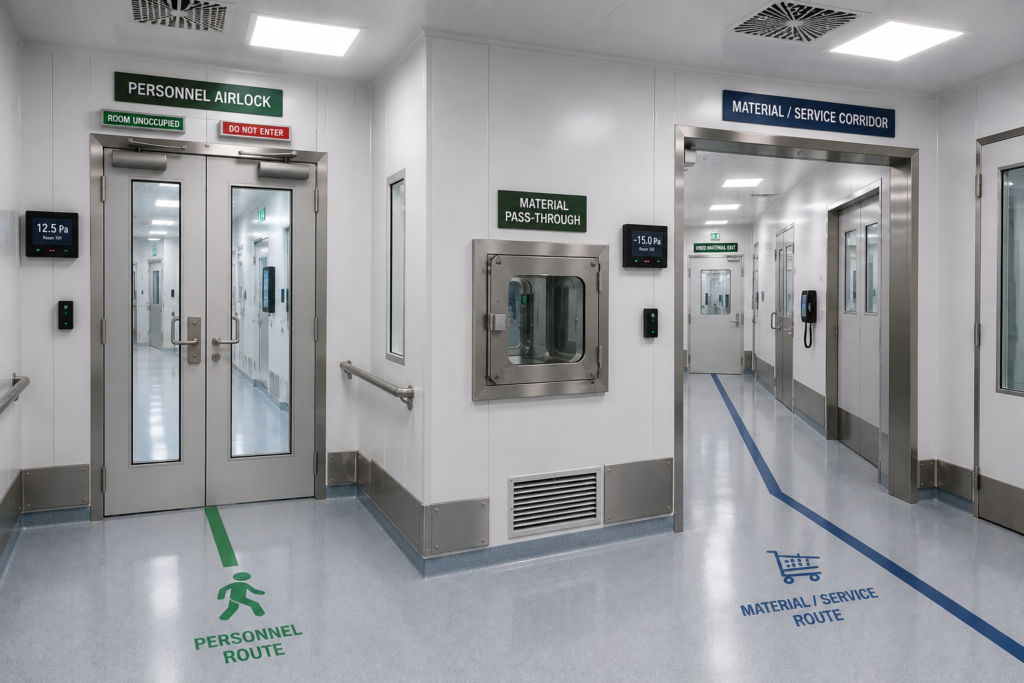
  • A double corridor design uses two separate circulation routes that can be configured to segregate personnel, materials, waste, clean and used equipment, or service access depending on the facility requirements. This arrangement can be useful in sterile, containment or other higher-risk manufacturing areas where additional segregation is justified, but it is not a universal GMP requirement for these facilities.
  • For sterile facilities specifically, EU GMP Annex 1 requires airlocks for personnel and materials moving between different grades and states that personnel airlocks should, wherever possible, be separated from those used for material movement. Where this is not practical, time-based separation can be considered. This requirement relates to controlled transfer and airlock design and should not be interpreted as a universal requirement for a double-corridor building configuration. https://health.ec.europa.eu/system/files/2022-08/20220825_gmp-an1_en_0.pdf

The Role of HVAC in Pharmaceutical Plant Layout

The Role of HVAC in Pharmaceutical Plant Layout

Layout and air handling cannot be designed independently of each other. Different rooms in a pharmaceutical facility design have different requirements for temperature, humidity, air pressure, and particle count. The HVAC system helps control these conditions according to the classification, process and contamination-control requirements of each room.

HVAC and layout work together in a few ways:

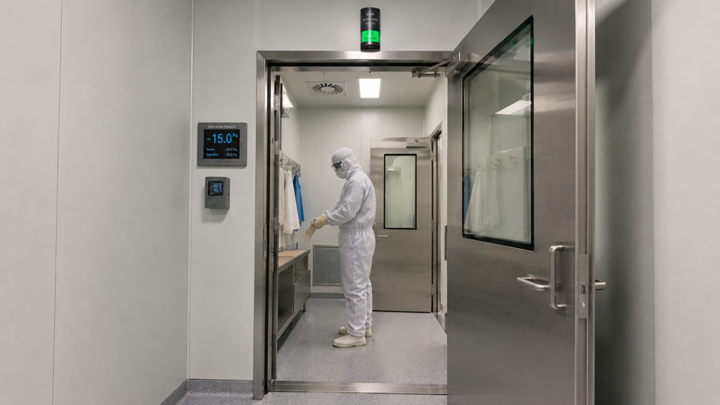
  • Pressure cascades in sterile product-protection areas direct the flow of air from cleaner areas to less clean areas to prevent contamination from flowing backward into a controlled area. Where highly toxic, potent, pathogenic or other hazardous materials require containment, the pressure regime may need to be modified, including the use of negative-pressure or pressure-sink arrangements to protect surrounding areas.
  • Room adjacency is important because it is easier and cheaper to route HVAC ductwork where rooms of similar air classification are adjacent to each other.
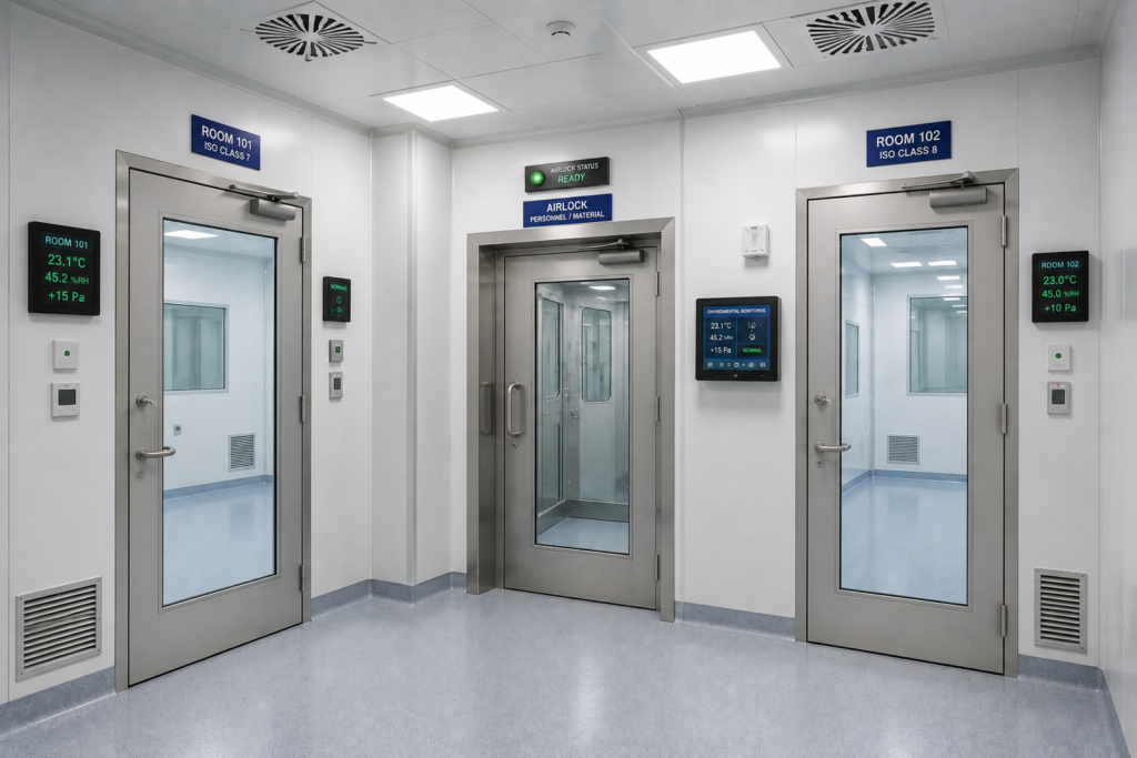
  • Airlocks between areas of different classification will be located on the basis of the layout so they are positioned where personnel, materials or equipment cross controlled boundaries.
  • High-potency or sterile zones may require dedicated or segregated air-handling systems depending on product risk, cross-contamination potential, containment requirements and the facility’s contamination-control strategy, so the layout must provide for the necessary mechanical space.

If you skip this coordination, it can show up later as expensive rework, extra ductwork running through finished ceilings, or rooms that cannot consistently achieve their required environmental conditions without redesign.

Factors That Influence Layout Choice

The main factors that normally dictate the layout right for a particular plant are as follows:

  1. Product range: A single, high-volume product can favour a product layout. A mixed portfolio may be better suited to a process, cellular or hybrid layout.
  2. Production volume: A high, steady volume favours a straight-line product layout. Lower, variable volume is better suited to a flexible process layout.
  3. Risk of contamination: High-potency and sterile products require more rigorous segregation and contamination-control or containment strategies. The appropriate pressure regime, airlock configuration and corridor philosophy should be established according to product and process risk.
  4. Space available: On a small site, you may need a more vertical or clustered layout. On a large site, you can be more spread out and linear.
  5. Later expansion: A layout that allows you to add lines or zones later will save you major rework versus one that’s built at full capacity from day one.
  6. Regulatory market: Facilities supplying the US, EU, or other regulated markets require layouts that demonstrate controlled, risk-based material, personnel and product flows and adequate measures to prevent contamination and mix-ups.

Pharmaceutical Facility Design and Construction

The choice of a layout type is only the first step. That choice becomes a working plant by bringing together architecture, process engineering, HVAC, utilities, electrical systems, automation and CQV planning, ideally from the very beginning of the design process, rather than as separate handoffs. Early multidisciplinary coordination helps align equipment integration, room relationships, material and personnel flows, maintenance access and supporting engineering systems.

That is where an integrated pharmaceutical engineering approach becomes important. Pharma Access supports this spectrum, from early layout planning to engineering, procurement, construction and commissioning and qualification, on projects across API, biotech and sterile manufacturing facilities. The layout decision is carried through to the finished building by an integrated project team so the HVAC design, corridor separations, and equipment locations stay aligned rather than being changed piecemeal during construction.

Common Mistakes in Pharma Plant Layout Design

In real projects, some common layout mistakes keep appearing:

  • Choosing a layout type without knowing the product mix: A plant that must later process multiple products can be locked into a product layout, resulting in costly rework.
  • HVAC as a stand-alone project: Air handling has to be part of the layout conversation from the start, not an afterthought once the rooms are already in the layout.
  • Not recognising corridor needs: Often, a corridor designed for a small pilot line cannot handle the traffic when production is ramped up.
  • Ignoring future growth: The compact, fully developed design offers no opportunity to add capacity without major redevelopment.
  • Early elimination of contamination control zoning: Layout has to segregate areas with different contamination-control or containment requirements from day one, rather than trying to correct the zoning strategy after equipment is already installed.

Read More: Turnkey Pharmaceutical Plant in Saudi Arabia

Why Integrated Pharmaceutical Facility Engineering Matters 

Pharmaceutical manufacturing facilities involve increasingly complex requirements across regulated markets. An integrated pharmaceutical engineering team with hands-on layout experience can save a plant from the above mistakes before construction starts. A team that has experience in process, product, and cellular layouts in different dosage forms knows the questions to ask early: product mix, expected volume, target regulatory markets, process risks, containment requirements and future expansion needs.

If you are a pharmaceutical company in India that is looking to build a new facility or expand an existing one, it is generally a smoother build to work with a firm that can manage layout, engineering design, and construction all under one plan, as opposed to dealing with separate vendors for each piece. This is the kind of end-to-end support Pharma Access provides, helping plants take a layout decision and turn it into a facility that performs the way it was designed to.

Wrapping Up

The type of pharmaceutical plant layout a plant uses, be it process, product, or cellular determines everything from the flow of materials to the design of the HVAC system to the ease of future plant expansion. There is no one correct answer. The best layout will depend upon your product mix, production volume, and the regulatory markets you intend to serve. Clarify those factors early, and the layout decision becomes a lot easier to make well.

Frequently Asked Questions

What are the main types of pharmaceutical plant layout?

The three main types are process (functional) layout, product (line) layout, and cellular layout. The process layout groups similar equipment together, the product layout arranges equipment in the order of production, and the cellular layout combines the two. In practice, pharmaceutical facilities may also combine these approaches into a hybrid layout based on the requirements of different process areas. 

Why is unidirectional flow important in pharma plant layout? 

Unidirectional flow means that the materials move through the process in a controlled forward sequence—from raw material toward finished product—with unnecessary backtracking and crossovers minimised. This reduces mix-ups and cross-contamination. In the US, 21 CFR 211.42(b) requires the flow of components, materials and drug products through pharmaceutical buildings to be designed to prevent contamination; it does not universally prescribe one-way movement in every pharmaceutical area.

What is the difference between single and double corridor layouts? 

One corridor may be used for controlled movement of personnel and materials, with appropriate procedures and segregation controls. A double-corridor arrangement uses two separate circulation routes that can segregate personnel, materials, waste, equipment or service movement depending on the facility’s operating philosophy. The additional separation can minimize undesirable crossover and contamination risks, but a double-corridor layout is not universally required for sterile or high-potency manufacturing facilities.

How does HVAC affect pharmaceutical plant layout? 

HVAC helps control the air pressure, temperature, humidity and airborne particulate conditions in each room. HVAC planning should occur alongside layout planning, not after, because layout decisions affect how easily pressure cascades can be achieved and how ductwork can be routed. The pressure strategy should also reflect whether the primary objective is product protection, containment, or both.

Which layout type is best for a new pharma plant? 

It depends on your product portfolio. Typically, a plant that produces a single product in large quantities is suited to a product layout; a plant that produces multiple products tends to be suited to a process or cellular layout. In many cases, a hybrid layout provides the most practical solution by applying different layout principles to different areas of the facility.

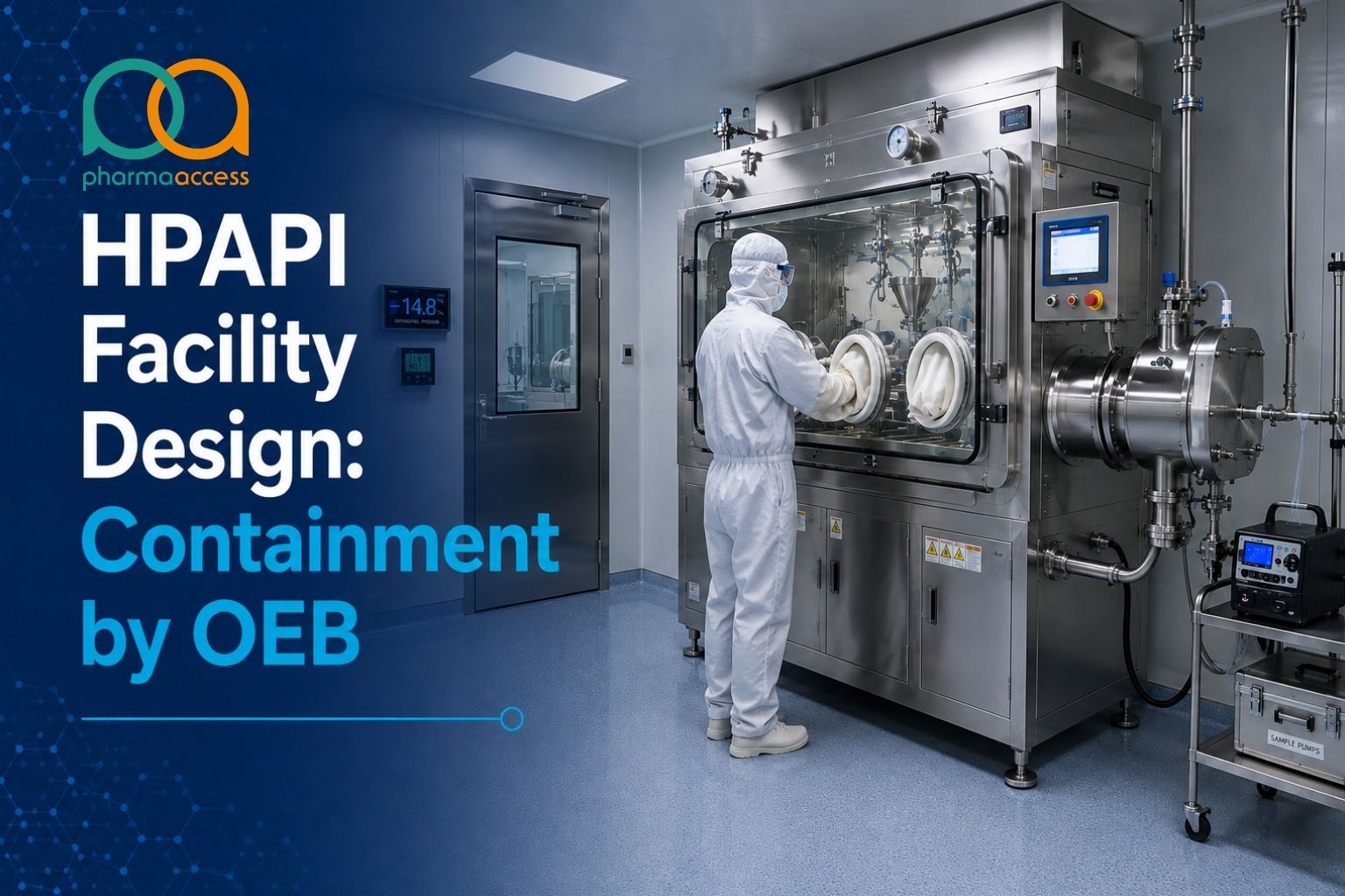
HPAPI Facility Design: How to Plan Containment by OEB Level

HPAPI Facility Design: How to Plan Containment by OEB Level

If your team is building or upgrading a plant to handle highly potent active pharmaceutical ingredients, containment is the first thing you need to get right. Late or incorrect containment decisions can create operator exposure risks, inspection findings, and costly rework after the building is already under construction. Get it right and you have a facility that protects people, supports global regulatory expectations, and runs with stable, controlled operations.

This post walks through HPAPI facility design in plain language, with a focus on Occupational Exposure Limits (OELs), Occupational Exposure Bands (OEBs) and how they guide every containment decision you make, from room layout to equipment selection and performance verification.

What Is an HPAPI, and Why Does Containment Matter?

A highly potent active pharmaceutical ingredient, or HPAPI, is a drug substance with high pharmacological or toxicological activity at low exposure levels. Think potent oncology compounds, certain hormones, cytotoxic APIs and highly active small-molecule intermediates. Because these materials can be active or harmful at very low exposure levels, even a tiny amount of airborne dust or residue can affect an operator’s health over time.

Here is why this matters for facility design: conventional API plants are built around cleanliness, product protection and worker safety. HPAPI plants require an additional, more stringent goal, protecting the people who work in them while also controlling cross-contamination. That additional goal drives decisions about room pressure, airflow, equipment type, and even how waste and gowning are handled.

What Is an Occupational Exposure Band (OEB)?

Before you design anything, you need to know the compound’s toxicological potency and the exposure level that must be controlled. That is what OEL development and Occupational Exposure Banding help establish. An OEL is a compound-specific airborne exposure limit, commonly expressed as an eight-hour time-weighted average, while an OEB groups compounds within an exposure range and can support decisions when a sufficiently robust compound-specific OEL is not yet available. 

Many pharmaceutical companies use five-band systems, but the numerical limits and band definitions are not globally standardized. At one end, OEB 1 generally covers materials with higher airborne exposure ranges and simpler control needs. At the other end, OEB 5 covers the most potent compounds, with occupational exposure limits below 1 microgram per cubic meter, often in the nanogram range.

It is also important not to use OEL/OEB and PDE/ADE interchangeably. OELs and OEBs support worker protection, while Permitted Daily Exposure (PDE) or Acceptable Daily Exposure (ADE) values are health-based limits used mainly to assess patient risk from cross-contamination and to establish cleaning limits in shared manufacturing facilities.

A simplified way to look at the bands is shown below. These ranges represent an illustrative five-band pharmaceutical scheme and should not be treated as a universal regulatory standard:

  • OEB 1: Higher exposure range, generally 1,000 µg/m³ or above. Good industrial hygiene, suitable ventilation and basic source controls may be sufficient, subject to a task-specific assessment.
  • OEB 2: OEL roughly 100 to below 1,000 µg/m³. Downflow booths, local exhaust ventilation or dust-controlled connections may be used depending on the operation.
  • OEB 3: OEL roughly 10 to below 100 µg/m³. Greater enclosure, glove bags, flexible isolators and closed transfer systems may be required based on the task.
  • OEB 4: OEL roughly 1 to below 10 µg/m³. High-performance primary containment, such as rigid isolators or an equivalent demonstrated system, is often considered.
  • OEB 5: OEL below 1 µg/m³, sometimes extending below 0.1 µg/m³. Very high containment, robust transfer, cleaning, maintenance and verification controls are required, with an isolator or equivalent demonstrated system selected according to the operation.

Your OEL or OEB assignment is not a guess. It comes from an evaluation of the compound’s toxicological potency and the health effects tied to exposure, usually done by a qualified occupational toxicologist or industrial hygienist before the design team finalizes the concept. The final containment strategy also considers process scale, quantity handled, dustiness, task duration and frequency, cleaning, maintenance and potential dermal exposure.

How OEB Levels Shape HPAPI Facility Design

How OEB Levels Shape HPAPI Facility Design

Once you know the OEL or applicable OEB, the design choices can follow a risk-based pattern, but the band alone does not prescribe a specific technology. Here is how it may play out at each stage.

OEB 1 and 2: Basic Engineering Controls

At the lower bands, the room design stays fairly close to a normal API facility. You still need good airflow, an appropriate ventilation and pressure strategy where required, and proper gowning procedures. The main additions may include local exhaust points at material transfer stations and dust-tight connections for charging and discharging powders.

OEB 3: Isolators and Closed Transfers

This is often the point where a plant moves from basic source control toward greater enclosure and contained transfer, although the exact solution depends on the task. Glove bags and flexible isolators may start showing up around reactors, dryers, and milling equipment. Room pressure cascades become more carefully coordinated rather than simply tighter, and airlocks with interlocks may be used according to the risk assessment between the process area and the corridor.

OEB 4 and 5: Full Containment

At OEB 4 and especially OEB 5, primary containment equipment and the supporting facility controls become more demanding. You are looking at rigid isolators or equivalent demonstrated systems, split butterfly valves for material transfer, dedicated or appropriately segregated air handling where required by risk assessment, suitable exhaust treatment and safe-change filtration where necessary, and monitoring of critical pressure and ventilation parameters.

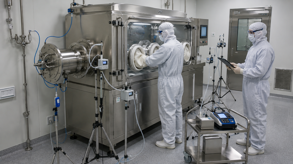
Occupational hygiene sampling and containment-performance testing are then used to demonstrate that exposure remains below the defined target before routine production begins.

Steps to Plan an HPAPI Facility

Validate before startup

Here is a practical order of operations for teams starting from scratch:

  1. Get the toxicology data first: You cannot design containment without knowing the OEL or applicable OEB and other relevant health hazards of the compound you plan to make.
  2. Map the process flow: Identify every point where the material is open to the room, such as charging, sampling, and packing, as well as cleaning, filter changes, maintenance and waste handling.
  3. Match the containment strategy to the OEL/OEB and task risk: Assign the right level of isolator, glove bag, or booth to each open point based on the exposure target, quantity, dustiness, duration, frequency and demonstrated containment performance.
  4. Design the room around the equipment, not the other way around: The pressure strategy, airlocks, and material and personnel flow should support the containment devices you have chosen.
  5. Plan for cleaning and decontamination: Every HPAPI area needs a documented method for appropriate dry or wet cleaning, decontamination, cleaning verification and safe waste removal. Product carryover limits should be based on the applicable HBEL/PDE/ADE, while occupational surface contamination should be assessed separately.
  6. Validate before startup: Run containment-performance testing using a surrogate powder and an established methodology such as SMEPAC on equipment to confirm it meets the defined containment-performance target before routine production begins.
  7. Train operators and maintenance personnel on the specific hazard: Generic gowning training is not enough at OEB 4 or 5. People need to understand what they are protecting against and why, including the requirements for cleaning, spill response, waste handling and actions following a containment breach.
  8. OEB classification addresses occupational health exposure, but it does not replace separate assessments for dermal exposure, sensitization, solvent hazards, chemical reactivity, static electricity or combustible dust. These risks need their own process-safety and industrial-hygiene controls. 

Building a Pharma Manufacturing Base With Containment in Mind

Many companies expanding into HPAPI production are not starting with a blank site. They are adding a containment suite to an existing plant, or converting part of a conventional API building. This is where planning early pays off. Retrofitting containment into a building that was not designed for it can require significant redesign, new HVAC interfaces and additional shutdown work.

When you are building a pharma manufacturing base that includes HPAPI capacity, a few things help keep the project on track:

  • Bring in OEL and OEB input before the architectural layout is locked.
  • Use dedicated or appropriately segregated HVAC strategies for high-containment zones, and justify any recirculation or exhaust arrangement through risk assessment.
  • Design corridors and airlocks with the material, waste and gowning flow in mind, not just square footage.
  • Plan utility routing (process gases, nitrogen, vacuum, clean compressed air, heating and cooling media, and the required water grade) around the containment equipment early, since retrofitting piping through a sealed isolator room later can create significant design and construction interfaces.

Firms that specialize in pharmaceutical engineering and containment integration often bring this experience to a project because they can coordinate equipment, facility, HVAC, utilities, cleaning and CQV interfaces together. Pharma Access works across engineering design, procurement and supplies, construction and installation, project management and CQV for pharmaceutical facilities, helping coordinate containment-related requirements with the wider facility design from the start.

Common Mistakes in HPAPI Facility Design

A few mistakes show up again and again on HPAPI projects:

  • Assigning the OEL or OEB too late: If toxicology data comes in after the layout is fixed, you end up retrofitting containment into a space that was not built for it.
  • Treating all HPAPIs the same way: An OEB 3 compound does not automatically need a containment solution intended for a much lower exposure range, and over-designing wastes money without adding real protection.
  • Ignoring the cleaning and decontamination strategy during design: If a room cannot be cleaned and decontaminated properly, cross-contamination risk goes up no matter how good the containment equipment is.
  • Underestimating airflow and pressure cascade design: A single poorly placed door or airlock can disrupt the intended airflow direction and weaken the facility’s secondary containment strategy.
  • Skipping operator training on the specific compound: Equipment only works as well as the people using it.

Why Work With Pharma Consultants in India

HPAPI manufacturing has created a growing need for pharma consultants who understand both global regulatory expectations and local construction realities. Working with a consultant who has handled containment integration before can reduce back-and-forth with equipment vendors and help resolve design interfaces earlier.

Full-service pharma project management services matter here too, since HPAPI projects touch process engineering, HVAC, architecture and civil work, automation, and CQV all at once. Coordinating these pieces without a single point of accountability can create interface gaps and delay decisions. 

Pharma Access provides integrated support across engineering design, procurement and supplies, construction and installation, project management and CQV, which is important on containment-heavy projects where systems and interfaces need to be coordinated from concept design onward.

Wrapping Up

HPAPI facility design comes down to more than one question at every stage: what is the OEL or applicable OEB of this compound, where can exposure occur, and do the room, the equipment, the cleaning systems, the transfer systems and the airflow around it match that hazard level? Get the toxicology data early, match your containment strategy to the actual exposure target and task risk, and build the room around the equipment rather than squeezing equipment into a fixed room later. That order of operations is what supports predictable HPAPI project delivery and, more importantly, keeps the people working in the facility safe.

Frequently Asked Questions

What does OEB mean in pharma facility design? 

OEB stands for Occupational Exposure Band. It’s a classification system that groups drug compounds within airborne exposure ranges using toxicological and health-effect information. It can support containment decisions, particularly when a sufficiently robust compound-specific OEL is not yet available, but it does not directly prescribe a particular containment technology.

What is the difference between an OEL and an OEB?

An OEL is a compound-specific airborne exposure limit. An OEB is a range used to group compounds according to toxicological potency or a corresponding exposure-control range. Where sufficient data are available, the compound-specific OEL provides the more precise target. 

How many OEB levels are there? 

Most pharma companies use a five-band system, OEB 1 through OEB 5. However, OEB schemes are company-specific and are not globally standardized. Some systems use numbers, while the NIOSH occupational exposure banding system uses bands A through E.

Do all HPAPI facilities need isolators? 

Not always. Lower exposure-risk operations may only need local exhaust ventilation or downflow booths. Isolators or equivalent high-performance containment systems may be required for lower exposure targets, but the selection should also consider the process, quantity, dustiness, duration, cleaning, maintenance and demonstrated equipment performance.

How early should containment planning start in a facility project? 

As early as possible, ideally before the architectural layout is finalized. Toxicology data and the OEL or applicable OEB assignment should come first, since they help determine room pressure, airflow design, material transfer, cleaning requirements and equipment choices later in the project.

What is the difference between an API facility and an HPAPI facility? 

A standard API facility focuses on product quality, cleanliness and worker safety. An HPAPI facility requires more stringent occupational-exposure and cross-contamination controls, which can mean added containment equipment, sealed transfer systems, specialized cleaning and waste-handling strategies, and dedicated or appropriately segregated air handling.

What is the difference between an OEL and a PDE/ADE?

An OEL is used to protect workers from occupational exposure, usually through an airborne concentration limit. A PDE or ADE is used mainly to assess patient risk from cross-contamination and to support cleaning-limit decisions in shared manufacturing facilities. The values address different exposure scenarios and should not be used interchangeably.

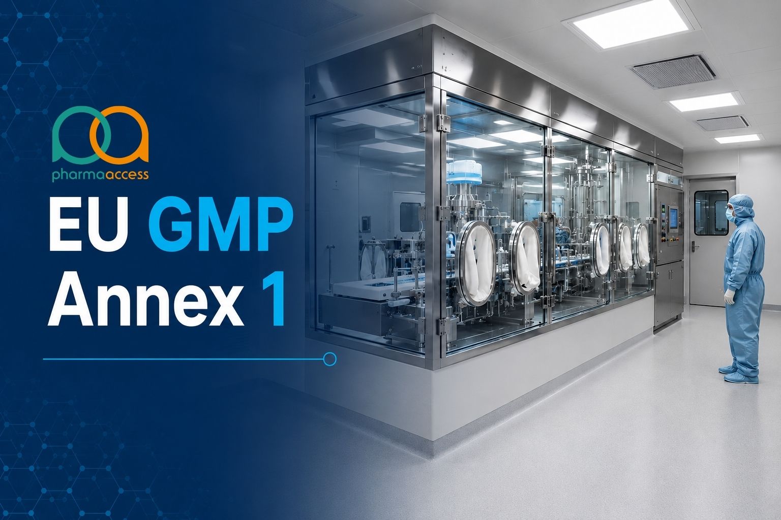
EU GMP Annex 1: Designing Compliant Sterile Facilities

EU GMP Annex 1: Designing Compliant Sterile Facilities

If your facility manufactures sterile products, EU GMP Annex 1 is probably the single document that shapes the most decisions on your design drawings. It touches your cleanroom layout, your air handling, your gowning rooms, and even how you validate filters. Getting it right at the design stage saves you from expensive rework once construction is already underway.

This post breaks down what the guideline actually requires, what changed in the 2022 revision, and what that means for how sterile facilities get designed and built today.

What Is EU GMP Annex 1?

EU GMP Annex 1 is the section of the European Union’s Good Manufacturing Practice guidelines that covers the manufacture of sterile medicinal products. It sits within EudraLex Volume 4 and sets out the expectations for cleanroom design, contamination control, aseptic processing, and environmental monitoring.

The annex was first published in 1971, but it went through a major rewrite that was finalized by the European Commission in August 2022 and came into operation on 25 August 2023, except for paragraph 8.123, which came into operation on 25 August 2024. This was the first full revision of Annex 1 following several partial revisions, and it substantially expanded the guideline, reflecting how much more detail regulators now expect from sterile manufacturers. 

Why the 2022 Revision Changed So Much

Here is the shift worth understanding. The older version of Annex 1 leaned more heavily on prescriptive requirements and did not define the same holistic, risk-based contamination-control framework.The revised version asks manufacturers to prevent contamination before it happens, through a documented, facility-wide approach called a Contamination Control Strategy (CCS).

A few things stand out about this revision:

  • It was developed jointly by the PIC/S and EMA Inspectors’ Working Group, in close cooperation with the European Commission and WHO, so the expectations now line up closely across EU, PIC/S, and WHO sterile-manufacturing guidance.
  • It applies a Quality Risk Management approach, meaning contamination controls need to be built into the facility and process from the start, not bolted on afterward.
  • Grade A areas now carry a stricter viable contamination limit, stated as “No growth,” with any microbial growth requiring an investigation.

The Contamination Control Strategy (CCS): The Core Requirement

The Contamination Control Strategy (CCS): The Core Requirement

If there is one concept to understand about this guideline, it is the CCS. A Contamination Control Strategy is a documented, facility-wide strategy that may reference several connected systems and explains how a facility identifies, prevents, detects, monitors, and controls contamination risks across the entire production process.

The CCS is not a paperwork exercise you complete after the facility is built. It needs to cover:

  1. Facility and equipment design. How the layout, airflow, and material flow reduce contamination risk from the ground up.
  2. Personnel practices. Gowning procedures, movement patterns, and training that limit human-sourced contamination.
  3. Environmental monitoring. Ongoing particle and microbial monitoring that provides evidence that the facility continues to perform as intended, not just on the day it was qualified.
  4. Process controls. Aseptic technique, filter integrity testing, and sterilization validation tied directly to the risk profile of each product.

The CCS should also address utilities, raw materials, product containers and closures, supplier and outsourced-activity controls, cleaning and disinfection, preventive maintenance, sterilization, process validation, CAPA, trend analysis, and continual improvement. 

Because the CCS spans design through operation, it has to be considered from the earliest facility planning stage, not added as a compliance document once construction wraps up.It should also be actively reviewed and updated where appropriate, with its effectiveness forming part of periodic management review. 

Cleanroom Grades Under the Guideline

The annex defines four cleanroom grades, A through D, based on particle and microbial limits. Each grade maps to a different level of risk in the manufacturing process.

  • Grade A: The critical zone. This covers aseptic filling lines, stopper bowls, open primary packaging, and any point where the product or its containers are directly exposed. First-air protection and appropriate airflow must be demonstrated over exposed sterile products, components, and critical surfaces. Unidirectional airflow is required for conventional Grade A zones, RABS, and open isolators, while airflow may not be fully unidirectional in closed isolators used for simple operations.
  • Grade B: The background environment surrounding Grade A operations where an isolator is not used. Aseptic RABS normally require at least a Grade B background, while open isolators generally require at least Grade C and closed isolators at least Grade D, based on risk assessment and justification within the CCS.
  • Grade C and D: Support areas for lower-risk stages, such as preparing solutions or components before they move into higher-grade zones. They can also be used for the preparation or filling of terminally sterilized products, depending on the operation and assessed risk.

Getting the grading right at the design stage determines nearly everything else downstream, from HVAC sizing to how many airlocks and gowning stages your layout needs.

The choice between terminal sterilization and aseptic processing should also be established early. Annex 1 expects finished products to be terminally sterilized wherever possible because a validated and controlled terminal sterilization process provides greater sterility assurance than sterile filtration or aseptic processing alone. This decision directly affects cleanroom grades, equipment selection, material flows, and the overall facility layout. 

Designing a Facility Around the Guideline From Day One

A common mistake is treating the annex as a testing checklist to satisfy near the end of a project. The revision makes clear that contamination control has to start on the drawing board.

A few design principles carry real weight under the current guidance:

  • Early barrier-technology evaluation: The annex places heavy emphasis on separating personnel from the product, requiring RABS, isolators, robotic systems, and other appropriate technologies to be considered to maintain the required conditions with less reliance on human intervention.
  • Airflow modeling before construction: Using CFD and design-stage airflow studies to assess unidirectional airflow patterns and pressure cascades on paper, before pouring concrete, can help identify potential dead zones before the room is built. Airflow predictions must then be verified through physical airflow visualization studies during qualification, both at rest and in operation, including representative interventions, while pressure relationships must be verified through qualification testing and monitoring.
  • Material and personnel flow separation: Layouts need clear, risk-based paths that minimize crossing and backtracking for people, materials, and waste to prevent contamination between clean and less-clean zones. Separate personnel and material airlocks should be provided wherever practicable, with unidirectional transfer arrangements used for materials entering and leaving Grade A and B areas. Where complete physical separation is not possible, risk-assessed time separation and procedural controls should be established.
  • Built-in monitoring points: Continuous total-particle monitoring during critical processing and continuous viable air monitoring in Grade A, with a similar risk-based approach considered for Grade B, need sensor and sampling locations designed into the room, not retrofitted later.

An integrated pharmaceutical engineering design approach brings these principles together at the concept and detailed design stage, so the facility’s physical layout supports the CCS instead of working against it.

Where CQV Services Fit Into Compliance

Where CQV Services Fit Into Compliance

Design intent only matters if it can be proven. This is where CQV services for pharmaceutical facilities become part of the compliance story, not a separate afterthought. Commissioning confirms the systems work as installed. Qualification, beginning with Design Qualification and continuing through IQ, OQ, and PQ, provides documented evidence that the design is suitable, the systems are correctly installed, and the facility operates and performs as intended. Qualification, validation, environmental-monitoring trends, deviation investigations, and CAPA tie it all together with documented evidence that the controls defined within the CCS remain effective under routine production conditions. 

Under the revised guideline, this evidence chain matters more than ever. Regulators expect to see aseptic process simulation records for aseptic processes, installed HEPA filter integrity test records, sterilizing-grade process-filter integrity test records where sterile filtration is used, and environmental-monitoring trend data that support the effectiveness of the controls described in the CCS. A facility that cannot produce this evidence, regardless of how well it was designed, will have difficulty demonstrating an effective state of control during inspection.

Common Pitfalls Facilities Run Into

A few issues show up again and again when facilities try to retrofit compliance instead of designing for it from the start:

  • Underestimating airlock and gowning requirements, which forces awkward layout changes mid-construction.
  • Treating the CCS as a document exercise instead of a living strategy tied to actual facility operation and monitoring data.
  • Skipping early filter and barrier technology decisions, which then constrain HVAC and room layout choices later in the project.
  • Insufficient personnel flow separation, leading to cross-contamination risks that only surface during environmental monitoring after startup.

Why Local Expertise Matters for Global Compliance

This EU guideline sets a widely used international benchmark, but applying it correctly depends heavily on local construction practices, climate conditions, and regulatory context. Working with experienced pharmaceutical engineering consultants in India means your facility design accounts for both the international standard and the practical realities of building and operating in your specific market.

Pairing that engineering expertise with project-specific input from quality, microbiology, and regulatory specialists who understand how EU, PIC/S, and WHO guidance is applied gives a facility a stronger position going into its first audit, rather than discovering gaps after the fact.

At Pharma Access, our engineering design and CQV teams work on sterile facility projects that need to meet this standard from the concept stage through validation. We handle cleanroom design, HVAC, utilities, monitoring requirements, and commissioning through one coordinated engineering and qualification approach, which helps facilities avoid the costly redesigns that come from treating contamination control as an afterthought. You can learn more about our approach on the Pharma Access about page.

Wrapping Up

The guideline asks manufacturers to think about contamination control as a design principle, not a final inspection hurdle. A facility built around a well-developed Contamination Control Strategy, with cleanroom grades, barrier technology, and monitoring points planned from the start, is better positioned to demonstrate consistent performance during qualification and maintain control over time. The earlier this thinking enters the design process, the less it costs to get right.

FAQs

What is the main change in the 2022 revision of EU GMP Annex 1? 

The revision strengthens the move away from relying on monitoring or end-product testing alone and toward a proactive, risk-based Contamination Control Strategy that covers facility design, personnel practices, and ongoing monitoring together.

What is a Contamination Control Strategy (CCS)? 

A CCS is a documented, facility-wide strategy that may reference several connected systems and explains how contamination risks are identified, prevented, detected, monitored, and controlled, spanning facility design, equipment, personnel, and monitoring, throughout the entire production process.

What are the cleanroom grades under this guideline? 

The annex defines Grades A through D. Grade A is the critical zone with the strictest limits, Grade B normally the background for Grade A aseptic processing where an isolator is not used, and Grades C and D support lower-risk stages of production. RABS and isolator background grades depend on the selected technology, process risk, and justification within the CCS.

Does this guideline only apply to EU-based manufacturers? 

No. EU GMP Annex 1 applies to sterile medicinal products manufactured under EU GMP requirements, including products manufactured outside the EU for supply to the EU or EEA market. PIC/S Annex 1 and WHO sterile-manufacturing guidance are closely harmonized with the EU text, but manufacturers must still consider the specific legal and regulatory requirements of every target market. 

When should compliance be considered during a facility project? 

From the earliest design stage. Retrofitting cleanroom grading, airflow, or barrier technology after construction is far more costly than building the Contamination Control Strategy into the original layout.

Note: This article provides a general engineering interpretation of EU GMP Annex 1. It should be read together with the official guideline and should not replace project-specific quality, microbiological, or regulatory assessment. 

Types of Purified Water Generation Systems in the Pharmaceutical Industry

Types of Purified Water Generation Systems in the Pharmaceutical Industry

Water is used throughout pharma manufacturing. It goes into formulations, cleans equipment, and rinses containers before they ever touch a product. Because of that, a purified water generation system in pharmaceutical industry settings is not a side utility. It is a quality-critical utility that requires careful design, qualification, monitoring, and control.

This post breaks down the common types of purified water systems, how they work, and how to pick the right setup for your facility. We will keep things simple and skip the deep engineering jargon where we can.

What Counts as Purified Water in Pharma?

Purified water is water treated to remove dissolved solids, organic matter, and microorganisms until it meets pharmacopeial standards. Pharmacopeias such as USP, Ph. Eur., and IP establish requirements and guidance for pharmaceutical water quality. For USP Purified Water, chemical attributes such as conductivity and Total Organic Carbon (TOC) are compendial requirements, while microbiological quality is addressed through appropriate monitoring and system-specific control rather than a microbial limit within the Purified Water monograph itself.

Here is why that matters. Ordinary tap or ground water carries suspended solids, dissolved salts, organic compounds, and microbes that can throw off a formulation or fail a batch release test. A pharmaceutical facility generally uses water meeting applicable drinking-water requirements as the minimum feedwater for Purified Water generation, with further treatment applied to achieve the required pharmaceutical water quality.

The Two-Stage Approach: Pretreatment and Final Purification

The Two-Stage Approach: Pretreatment and Final Purification

Most purified water generation trains can be understood through two main treatment stages, and understanding this split makes the rest of this guide easier to follow. After generation, storage, distribution, sanitization, and monitoring become equally important for maintaining the required water quality up to the point of use.

Stage 1: Pretreatment

Pretreatment removes the large stuff first, so it does not damage sensitive equipment downstream. This stage may include multi-media filters, activated carbon filters, and water softeners to strip out particles, chlorine, and hardness before the water moves any further. The actual pretreatment sequence depends on feedwater quality and the requirements of the downstream purification system. 

Stage 2: Final Purification (Polishing)

The final treatment stage, sometimes called polishing, brings the water down to the target purity level often through reverse osmosis followed by electrodeionization where appropriate to further lower conductivity before storage. Additional steps such as UV treatment or ultrafiltration may be added depending on what the facility needs.

Common Types of Purified Water Generation Systems

Here are the main system types you will run into in pharma manufacturing.

1. Reverse Osmosis (RO) System

RO uses pressure to push water through a semipermeable membrane, rejecting a high proportion of dissolved salts, many organic contaminants, particulates, and microorganisms. It is often the workhorse of a purified water system because it can substantially reduce multiple contaminant classes in a single treatment stage.

2. Deionization (DI) System

DI systems pull ions out of water using resin beds charged to attract dissolved minerals. On their own, DI systems may be used within qualified pharmaceutical water-treatment trains, although they are often combined with other purification technologies rather than relied upon as the only treatment barrier.

3. Electrodeionization (EDI) System

EDI combines ion-exchange resins with ion selective membrane and  electric current to continuously remove dissolved ions without the chemical regeneration that older DI systems needed. An EDI module usually sits right after the reverse osmosis stage, where it removes residual ionic contaminants from RO permeate to help achieve the required conductivity. This is a big reason RO+EDI has become a common configuration in modern pharmaceutical Purified Water systems. 

4. Distillation System

Distillation boils water and collects the condensed steam, leaving contaminants behind. It remains a well-established technology for Water for Injection (WFI) production. Current pharmacopeial frameworks also permit appropriately designed and qualified non-distillation purification processes for WFI production. 

5. Ultrafiltration (UF) System

UF uses a membrane process designed primarily to retain microorganisms, colloids, macromolecules, and, in appropriately designed applications, reduce endotoxin burden rather than remove dissolved ions. It is often added at the end of a system when additional microbial, colloidal, or endotoxin control is required. It is not primarily a conductivity-polishing technology, and TOC measurement should not be treated as a substitute for microbiological or endotoxin control.

6. Hybrid Systems (RO + EDI)

Hybrid systems combining reverse osmosis and electrodeionization are widely used to achieve pharmaceutical Purified Water quality, with RO+EDI offering continuous ionic polishing without routine chemical regeneration of conventional ion-exchange resin beds. If you are specifying a new system today, this is often one of the configurations evaluated first, although the final treatment sequence should always depend on feedwater quality, required water quality, capacity, sanitization strategy, and operating requirements.

Purified Water vs. Water for Injection (WFI)

Purified Water vs. Water for Injection (WFI)

A quick point of confusion worth clearing up: purified water and WFI are not the same thing. Purified water is commonly used for non-parenteral formulations, equipment cleaning, and other applications where PW is the specified grade, while WFI is required for applications such as the manufacture of injectable products and specified final-rinse operations associated with injectable product-contact equipment and components. WFI also includes a bacterial endotoxin requirement and requires an appropriate microbiological control strategy. Choosing the right system depends heavily on which one your product line actually needs.

How HVAC Ties Into Water System Performance

A purified water system does not operate in isolation. The room housing it, along with the surrounding manufacturing areas, depends on properly functioning HVAC to control temperature, humidity, and other environmental conditions required for equipment, instruments, and manufacturing operations. HVAC supports the operating environment around the utility system, although water quality itself is primarily controlled through hygienic system design, circulation, sanitization, storage, and distribution.

This is where HVAC validation in pharmaceutical industry projects becomes relevant. HVAC qualification may include, as appropriate, design qualification (DQ), installation qualification (IQ), operational qualification (OQ), and performance qualification (PQ). Testing during this process may cover air changes per hour, airflow pattern and velocity, pressure differentials, temperature and humidity, filter leak testing, and particle counts, with the scope determined based on the facility, application, and risk assessment.

Poor HVAC control in a classified or controlled manufacturing area can undermine the environmental conditions required by the process. However, maintaining Purified Water quality still depends primarily on the design and operation of the water generation, storage, and distribution system rather than HVAC alone.

Monitoring and Control: The Role of a Building Management System

Modern pharma facilities do not run water and HVAC systems on manual checks alone. A pharmaceutical water system is commonly monitored and controlled through dedicated automation such as PLC/HMI or SCADA architecture, while BMS or EMS platforms may integrate selected facility and utility information depending on the overall control philosophy. 

A well-set-up automation and monitoring architecture gives your team real-time visibility into pressure, temperature, water-system parameters, operating status, and system alarms, so problems get caught before they turn into a failed batch or a finding during inspection. Where appropriate, selected water-system status and alarms may also be integrated into the facility BMS or supervisory platform, reducing the need for operators to rely on separate systems for basic utility visibility.

Choosing the Right System for Your Facility

A few questions can help narrow down which purified water generation system in pharmaceutical industry settings fits your operation:

  1. What is your feed water quality? Hard, high-mineral water needs heavier pretreatment before RO.
  2. What product types do you manufacture? Non-parenteral products commonly use Purified Water where it is the specified grade, while injectable formulations typically require WFI for formulation and certain final-rinse applications.
  3. What is your daily water demand? Higher volumes influence generator capacity, redundancy, storage volume, and lifecycle economics, but technology selection must still begin with the required water grade and quality specification.
  4. What are your TOC and conductivity targets? Conductivity requirements influence technologies such as RO and EDI, while UV, UF, or other treatment steps may be selected for specific organic, microbial, or endotoxin-control objectives depending on the system design.
  5. How will you sanitize the system? Hot water sanitizable skids reduce chemical use but need membranes, EDI modules, seals, instrumentation, and other system components rated for that heat.

Why Facility Design Matters as Much as Equipment Choice

Why Facility Design Matters as Much as Equipment Choice

Buying the right skid is only part of the job. Piping layout, storage tank design, and distribution loop configuration all affect whether purified water stays within spec between the generation point and the point of use. A poorly designed loop can allow stagnant conditions that encourage microbial proliferation, even with a solid generation system upstream. Hygienic design therefore also considers factors such as dead-leg minimization, drainability, appropriate tank design, circulation, sanitization, sampling points, and monitoring.

This is where working with experienced pharmaceutical utility engineers and consultants pays off. At Pharma Access, our engineering design team handles mechanical and utility system design, including water and HVAC systems, as part of full facility projects across India and other markets. We look at generation, storage, distribution, and the supporting facility systems as coordinated engineering packages instead of isolated design scopes, helping reduce the coordination gaps that can cause rework later. You can see more about how we approach clean utility systems, including Purified Water and WFI, on the Pharma Access Clean & Black Utilities.

Wrapping Up

There is no single “best” purified water system for every pharma facility. RO+EDI is a widely used configuration for pharmaceutical Purified Water generation, while WFI can be produced through distillation or appropriately designed and qualified non-distillation processes where permitted by the applicable pharmacopeial and regulatory framework. What matters most is matching the system to your feed water, your product line, and your validation plan, then backing it with hygienic storage and distribution, an appropriate sanitization strategy, monitoring, and integration with the wider facility utility and control systems.

FAQs

What is the most common purified water system used in pharma today? 

RO combined with EDI is one of the commonly used configurations for modern pharmaceutical Purified Water systems. It removes most contaminants through the RO stage and then uses electrodeionization to remove residual ionic contamination and achieve the required conductivity without routine chemical regeneration of conventional DI resin beds.

What is the difference between purified water and Water for Injection (WFI)? 

Purified water supports applications such as non-parenteral formulations and cleaning where PW is the specified grade. WFI is used for applications including injectable-product manufacture and specified final-rinse operations and includes a bacterial endotoxin requirement.

How often should a purified water system be validated? 

Most facilities qualify the system before routine use through defined lifecycle activities that include IQ, OQ, and PQ as applicable, followed by ongoing monitoring, trending, maintenance, change control, periodic review, and risk-based requalification where required. There is no single universal requalification interval that applies to every pharmaceutical water system.

Does HVAC really affect purified water quality? 

Indirectly, yes. HVAC maintains appropriate environmental conditions around equipment and manufacturing areas, but Purified Water quality is primarily maintained through hygienic water-system design, circulation, sanitization, storage, distribution, and monitoring.

Can one system handle both purified water and WFI needs? 

A facility may share elements of upstream feedwater or pretreatment infrastructure, but PW and WFI generation, storage, distribution, sanitization, and monitoring strategies must be designed according to their respective quality requirements and intended applications. The final system architecture should therefore be established through process requirements, applicable pharmacopoeias, and a documented risk-based design approach.

ICH Q13 Continuous Manufacturing: What It Means for Facility Design

ICH Q13 Continuous Manufacturing

If your plant is moving from batch production to continuous manufacturing, the facility design itself may need to change, not just the equipment inside it. ICH Q13 is the guideline that sets out the scientific and regulatory considerations for how continuous manufacturing (CM) should be developed, implemented, operated, and managed over its lifecycle. For anyone planning a new facility or converting part of an existing one, these principles can influence decisions long before the first piece of equipment gets installed. 

This post breaks down ICH Q13 in plain terms and walks through what it actually means for facility layout, automation, and day-to-day operation.

What Is Continuous Manufacturing?

In a batch process, you make a defined quantity of product and move it through manufacturing steps as a batch. Continuous manufacturing works differently. Materials are continuously fed into the process, transformed as they move through it, and output material is removed while the process is operating.

The guideline describes CM as the continuous feeding of input materials, transformation of in-process materials, and simultaneous removal of output materials from the manufacturing process. That single concept explains why facility design changes so much under CM. The facility is no longer planned only around a series of isolated processing steps. It’s planned around how connected operations interact and how material moves through the system.

Importantly, ICH Q13 makes clear that continuous manufacturing can apply to some or all unit operations. A manufacturing process can therefore combine batch operations with directly connected continuous operations rather than requiring the entire process to operate continuously.

What Is ICH Q13?

ICH Q13 is a guideline from the International Council for Harmonisation that covers the science and regulatory expectations behind continuous manufacturing of drug substances and drug products. Work on it began in 2018, a draft was endorsed for public consultation in July 2021, and the final Step 4 guideline was adopted on November 16, 2022. In the EU, the guideline became legally effective on July 10, 2023. The FDA issued its final Q13 guidance for industry in March 2023.

The guideline builds on earlier ICH quality guidelines such as Q8 (Pharmaceutical Development), Q9 (Quality Risk Management), Q10 (Pharmaceutical Quality System), and Q11 (Development and Manufacture of Drug Substances). It also includes a dedicated section, Annex III, that covers continuous manufacturing of therapeutic protein drug substances. The guideline also notes that its broader principles may apply to other biological and biotechnological entities.

At its core, the guideline addresses process development, control strategy, process dynamics, equipment design and system integration, process monitoring and control, process validation, and lifecycle management, all under one connected approach.

How ICH Q13 Shapes Facility Design

How ICH Q13 Shapes Facility Design

Here is where the guideline turns into real construction and layout decisions.

  • Equipment footprint can shrink, but connections multiply: CM system design can enable process simplification or intensification and, in some cases, reduce the number or size of unit operations, although a smaller facility footprint is not guaranteed. Integrated equipment also has to connect and interact as a system, which means piping, transfer interfaces, instrumentation, sensors, control cabling, and maintenance access need careful planning from the start.
  • Process monitoring becomes part of the room design: Where Process Analytical Technology (PAT), in-line, on-line, or other process measurements are used, the facility needs suitable instrument locations, power, data connectivity, sampling access, and maintenance access built in rather than added later. PAT is well suited to CM under ICH Q13, but it is not a universal requirement for every continuous process.
  • Material diversion needs a physical path: When the monitoring and control strategy identifies potentially non-conforming material, the system may need to divert that material away from acceptable product according to predefined criteria. That diversion path is a design decision, not just a software setting.
  • Process dynamics influence physical configuration: Residence Time Distribution (RTD) describes how long material spends moving through a process and is influenced by factors such as equipment design and configuration. Understanding RTD and process dynamics supports material tracking and helps determine appropriate sampling and diversion strategies, making equipment arrangement and connections important engineering considerations.
  • Utilities need to support the planned operating profile: Compressed air, nitrogen, process water, power, and other required utilities need to be evaluated against the intended run duration, simultaneous demand, operating range, and required system reliability rather than automatically being sized for round-the-clock operation.
  • Automation and control infrastructure take on a bigger role: With CM, the control system tracks the process in real time, so automation architecture, operator interfaces, control-panel locations, and data infrastructure become core parts of the facility design alongside the process room itself.

Steps to Plan a Facility Around ICH Q13

Here is a simple order of operations for teams starting a CM project:

  1. Define the process train early: Know which unit operations will run in a connected line and which, if any, will remain in batch mode before you sketch the room layout.
  2. Map monitoring and sensor locations. Decide where the process needs real-time monitoring, including PAT where appropriate, then design power and data access around those points.
  3. Plan the material diversion and collection path: Build a physical route for potentially non-conforming material that keeps it separate from acceptable products and supports the defined material-disposition strategy.
  4. Size utilities for the planned operating profile: Confirm that compressed air, nitrogen, process utilities, and power supply can handle the intended run duration, simultaneous loads, and required reliability.
  5. Design the automation infrastructure alongside the process room: Treat data infrastructure, control panels, operator interfaces, and cable routing as core parts of the layout, not an add-on.
  6. Build in a validation strategy that supports the state of control: CM can use traditional process validation or continuous process verification, depending on the process and justification. The facility, automation, and monitoring systems therefore need to support the data collection required for the selected validation approach throughout the manufacturing run.
  7. Train operators for a connected process: Running a CM line calls for a different skill set than managing discrete batch steps, so training plans should reflect that.

ICH Q13 also treats start-up, shutdown, pauses, restarts, and unplanned disturbances as important transient events. Their impact on material quality and process dynamics should therefore be understood when developing the operating and control strategy. 

Building Pharma Facilities Around Automation

Building Pharma Facilities Around Automation

Moving to continuous manufacturing usually means moving toward higher levels of integrated automation around the CM process, rather than simply automating individual pieces of equipment. This is where pharma manufacturing automation and facility design have to work together from day one. A control system that can manage real-time diversion, batch definition, and data capture only works if the physical layout supports it, with the right cabling paths, panel locations, and access for maintenance.

Companies offering pharma engineering solutions increasingly build this thinking into early-stage design rather than treating automation as a later add-on. Pharma Access brings process design, automation, utilities, facility engineering, and CQV considerations together during engineering development across its pharmaceutical projects, so the systems can be coordinated before construction starts.

Common Mistakes in ICH Q13-Aligned Facility Design

A few issues show up often when teams move to CM without planning the building around it:

  • Treating automation as a bolt-on: Retrofitting sensors, cabling, and control panels into a finished room can create avoidable rework and integration complexity compared with designing them into the facility from the start.
  • Underestimating utility demand: Longer CM runs can create sustained equipment and utility loads, and supporting systems designed only around intermittent batch operating profiles may not suit the intended CM run duration or operating range.
  • Skipping the diversion path in early layouts: Without a planned route for potentially non-conforming material, teams end up improvising later, which can complicate operation, qualification, and the material-diversion strategy.
  • Ignoring process dynamics and RTD: Changing equipment arrangement, connections, or hold-up volumes without understanding their effect on material movement can affect traceability, sampling, and diversion decisions.
  • Forgetting operator training needs: A connected line runs differently than a batch process, and operators need to understand the new failure points.
  • Designing the process room without the automation infrastructure in mind:Data infrastructure, operator interfaces, controls, and equipment connections have to develop alongside the process rather than being squeezed in afterward.

Why Work With Pharma Turnkey Consultants

CM projects bring process engineering, equipment integration, automation, utilities, facility design, and validation together at the same time which is a lot to coordinate without a single team managing the full picture. That is where pharma turnkey consultants add real value, since they carry a project from early engineering design through construction, procurement, and commissioning under one plan instead of handing it off between separate vendors at each stage.

Pharma Access works this way across its projects, offering engineering design services for pharma clients alongside construction, procurement, and commissioning, qualification, and validation (CQV) support. For a CM project, having one team track the process design, the automation plan, and the physical build together helps catch conflicts early, before they turn into rework.

Wrapping Up

ICH Q13 gives the industry a shared set of expectations for continuous manufacturing, but meeting those expectations comes down to how well the facility is built around the process. Map the process train early, plan for real-time monitoring and material diversion, understand process dynamics and RTD, size utilities around the intended operating profile, and treat automation and data infrastructure as part of the core layout. Get that sequence right, and the facility supports the process instead of working against it.

Frequently Asked Questions

What is ICH Q13? 

ICH Q13 is a guideline that sets scientific and regulatory expectations for continuous manufacturing of drug substances and drug products. It covers process development, control strategy,process dynamics, equipment design and system integration, process monitoring and control, process validation, and lifecycle management under one connected approach.

When did ICH Q13 become effective? 

The final guideline was adopted on November 16, 2022, and it became legally effective in the EU on July 10, 2023. The FDA issued its final Q13 guidance in March 2023. Different regions have their own timelines for adopting ICH guidelines into local regulation.

How is continuous manufacturing different from batch manufacturing? 

In batch manufacturing, product moves through manufacturing steps as defined batches. In continuous manufacturing, materials are continuously fed, transformed, and removed while the process operates. ICH Q13 also allows some unit operations to remain in batch mode while other directly connected operations run continuously.

Does ICH Q13 apply to biologics? 

Yes. ICH Q13 applies to continuous manufacturing of chemical entities and therapeutic proteins. Annex III specifically addresses continuous manufacturing of therapeutic protein drug substances, while the guideline notes that its principles may also apply to other biological and biotechnological entities.

What facility changes does continuous manufacturing usually require? 

Plants may need integrated equipment arrangements, defined material-transfer interfaces, suitable monitoring and sampling locations, material-diversion and collection points, automation and data infrastructure, utilities matched to the intended operating profile, and sufficient access for operation and maintenance. The exact facility changes depend on the process and CM configuration.

Does ICH Q13 require Process Analytical Technology (PAT)?

No. ICH Q13 states that PAT is well suited to continuous manufacturing and provides examples of its use for process monitoring and control, but it does not make PAT a universal requirement for every CM process. The monitoring strategy should be appropriate to the process and its control strategy. 

Does continuous manufacturing eliminate pharmaceutical batches?

No. ICH Q13 retains the concept of a batch for continuous manufacturing. Batch size can be defined by the quantity of output material, quantity of input material, run time at a defined mass flow rate, or another scientifically justified approach, and it can also be established as a range.

Brownfield Pharma Upgrades Without Shutting Down Production

Brownfield Pharma Upgrades Without Shutting Down Production

“Most manufacturers can’t afford to shut down a pharma plant for months. Every day of lost production is lost revenue, extended production interruptions can also affect medicine supply continuity. But older facilities still need new cleanrooms, upgraded HVAC, increased capacity, and equipment and systems aligned with current GMP requirements. That tension is precisely what brownfield pharma upgrades are meant to solve, upgrading a live facility while keeping unaffected operations running wherever technically and GMP-feasible.

In this post, we’ll look at how that actually happens, from planning through construction, in plain language.

What is a Brownfield Pharma Project?

Brownfield projects are projects to expand, renovate, or upgrade an existing facility, often an already in-production facility. This isn’t like a greenfield project, where a new facility is developed without having to retrofit around an existing operating process or facility infrastructure.

There are real constraints to working on the brownfield facility. You are dealing with existing column grids, fixed ceiling heights, and utility entry points that were put in place years ago for a different process. Plus, the site usually needs to continue making products and maintaining GMP control and inspection readiness while the construction crew is there.

Why Keeping the Plant Running Is So Hard

There are a couple of things that make this particularly challenging:

  • Increased risk of contamination: Dust, vibration, and open construction zones near a cleanroom can jeopardise product quality if not carefully managed.
  • Personnel and material flow must remain controlled: Operators still have to go through the building, and materials still have to reach the production areas through controlled and appropriately segregated routes without uncontrolled crossover with construction activities. FDA 21 CFR 211.42 requires material and component flows through pharmaceutical buildings to be designed to prevent contamination. 
  • Shared utilities create critical interfaces: Power, compressed air, water systems, and HVAC often feed both the operating area and the area being upgraded, so a mistake in one can impact the other.
  • Regulatory documentation must be kept current: As the facility changes, even if it is still operating, change control, affected qualification and validation documentation, SOPs, and the Site Master File where applicable and where the changes affect its contents need to be updated. EU GMP Annex 15 requires planned changes that may affect product quality to be formally documented and their impact on the validated status or control strategy assessed. PIC/S also states that a Site Master File should be regularly reviewed so that it remains representative of current activities. https://health.ec.europa.eu/document/download/7c6c5b3c-4902-46ea-b7ab-7608682fb68d_en

These are not new issues for experienced project teams, but they do call for a different playbook than starting with a blank slate.

How to Plan Brownfield Upgrades Without Shutting Down

How to Plan Brownfield Upgrades Without Shutting Down

Here is a practical order to keep production running during a brownfield project:

  1. First, do a full facility audit: Assess the building structure, existing utility capacity, cleanroom classifications, and current validation status before any design work begins. Existing drawings, HVAC zoning and pressure relationships, personnel and material flows, equipment interfaces, and available shutdown windows should also be verified where relevant. Where the proposed change may affect product quality or the validated state, it should be formally assessed through change control and Quality Risk Management. This is the foundation for all subsequent decisions.”
  2. Divide the project into phases: Break the work into sections that can be done one at a time instead of doing one large renovation so that only a small part of the plant is offline at any one time.
  3. Keep construction and production areas physically separated: Temporary walls, sealed barriers, and dedicated construction corridors keep dust and people away from live manufacturing areas.
  4. Arrange utility tie-ins during planned downtime: Critical tie-ins to shared power, water, HVAC, compressed air or other GMP-supporting utilities should be executed during approved shutdown, maintenance or controlled cutover windows where required, with appropriate isolation, sequencing and contingency planning. Not every tie-in requires the entire facility to stop production; the extent of shutdown should depend on the affected system, available redundancy, segregation and documented risk assessment. EU GMP Annex 15 requires planned facility and utility changes that may affect quality to be documented and assessed using a risk-based approach.
  5. Update documentation along the way: As construction proceeds, change control records, SOPs, and affected qualification and validation documents are updated through controlled procedures, rather than being retrospectively corrected after execution. Significant changes to an approved qualification or validation protocol during execution should be documented, scientifically justified and handled through the applicable deviation or change procedure. EU GMP Annex 15 specifically requires qualification and validation documentation to be approved and significant changes to approved protocols during execution to be documented and justified.
  6. Re-qualify affected systems before returning them to GMP use: When a section is finished, the affected facilities, utilities, equipment and systems undergo the required commissioning, qualification and/or validation activities before production resumes there. The extent of requalification should be based on the change-impact assessment and Quality Risk Management, rather than assuming that every system requires the same level of requalification. Properly segregated work on another phase may continue where the documented risk controls allow it. EU GMP Annex 15 states that qualification and validation scope should be based on justified and documented risk assessment and recognises requalification where applicable.

For sterile manufacturing areas, brownfield modifications should also be assessed against the facility’s Contamination Control Strategy (CCS), including potential impacts on premises, HVAC, airflow, pressure relationships, utilities, personnel and material movement, cleaning, monitoring and qualification. EU GMP Annex 1 requires a facility-wide CCS and states that changes to contamination-control systems should be assessed for their impact on that strategy.

Arrange Utility Tie-Ins During Planned Downtime

Techniques That Keep Production Running

Techniques That Keep Production Running

Some particular methods are consistently useful on well-planned brownfield jobs:

  • Construction in segments or phases: The plant doesn’t have to shut down entirely, only part by part, by breaking the project into phases.
  • Temporary containment barriers: Partitions are sealed, and where justified by the contamination-control strategy and pressure design, construction areas may be maintained at a lower pressure relative to adjacent controlled areas to help contain dust and particles, provided this does not compromise the established cleanroom pressure cascade or airflow pattern. FDA GMP requires appropriate control of air pressure and dust where relevant, while EU GMP Annex 1 makes pressure relationships dependent on facility design, contamination risk and containment requirements rather than prescribing negative pressure universally.
  • Separate construction access ways: Contractors and materials are provided with a separate entry and exit path so that they do not cross paths with production staff wherever practicable .
  • Weekend and off-hours working windows: Loud or otherwise disruptive work, such as cutting into walls or running new ductwork, is often scheduled outside of normal production shifts.
  • Modular or pre-fabricated components: By building pre-fabricated utility assemblies, ductwork sections, cleanroom components or skid-mounted equipment off-site and then quickly installing them on site, construction crews spend less time inside the operating facility.

Common Risks During Live Facility Upgrades

Some risks are so frequent that they deserve planning attention from day one:

  • Underestimating utility capabilities: New equipment or line expansions often require more power, compressed air, or water than the existing system was designed to provide.
  • Poor phase-to-phase sequencing: If an upgraded area is returned to GMP use before the required commissioning, qualification, validation and applicable quality release activities are complete, you can create compliance gaps that become difficult to resolve later. EU GMP Annex 15 requires qualification and validation activities to follow planned and approved stages and allows formal release to subsequent qualification stages based on documented assessment.
  • Poor communication with production teams: Construction schedules that do not reflect actual production runs cause conflicts and delays on both sides.
  • Incomplete as-built documentation: In older facilities, the drawings may be obsolete, and planning gets bogged down until a new survey fills in the blanks.
  • Treating contamination control as an add-on in construction: Any short-term disturbance of dust or airflow in the vicinity of a live cleanroom can threaten the controlled environment and potentially product quality. GMP requirements emphasise control of contamination, dust, ventilation and airflow within pharmaceutical manufacturing environments.

Pharma Construction and Installation Services That Support This Work

Brownfield projects require construction teams who know how to work in a live GMP environment, not just how to build.” Pharma construction and installation services focused on this type of work typically have experience with phased scheduling, containment barriers, and working around active production, rather than treating each project as a greenfield build.

Pharma Access supports greenfield and brownfield pharmaceutical projects through integrated engineering, procurement, construction and installation, project management, commissioning, qualification and validation capabilities. Coordinating engineering design and construction within an integrated project team can help keep the phasing plan, utility tie-ins and qualification schedule aligned instead of treating these as separate interfaces when the plant cannot accommodate a prolonged shutdown. 

Pharma Access’s construction and CQV capabilities cover pharmaceutical HVAC, utilities, cleanrooms, mechanical, electrical and piping installations together with qualification and validation support. 

Why Brownfield Projects Need Integrated Pharmaceutical Engineering 

Brownfield projects often involve more live interfaces and simultaneous disciplines than a comparable greenfield build, because the plan has to take the existing structure, live operations, and updated regulatory expectations all into account together. An experienced pharmaceutical engineering team that has done this type of project before knows what to look for in the audit phase and where older facilities tend to have issues, be it aging HVAC, limited utility capacity, or gaps in the existing qualification and validation status.

For a pharmaceutical manufacturer, the choice between a plant upgrade and a greenfield project is often driven by factors such as time, budget, available utility capacity, future expansion requirements, production-disruption risk, and the ability of the existing site to meet the technical needs of the new process. An engineering partner who has done greenfield and brownfield work can clearly lay out that comparison before construction locks in decisions that are costly to change later.

Wrapping Up

Production can often continue in unaffected areas while critical interventions are confined to planned shutdown or cutover windows. First, audit the facility; break the project into phases; keep construction physically separate from live areas; and qualify affected systems before they are returned to GMP use. 

This way, a plant can add capacity, meet new GMP standards, or modernise ageing systems while reducing the duration and extent of shutdowns rather than assuming that every brownfield project can proceed with zero interruption. EU GMP Annex 15 supports a lifecycle and risk-based approach to qualification, validation and facility design changes, while FDA GMP requirements focus on protecting manufacturing operations from contamination and maintaining appropriate environmental controls.

Frequently Asked Questions

What does brownfield mean in pharma manufacturing? 

‘Brownfield’ means taking an existing pharmaceutical facility and either growing it, renovating it, or upgrading it, often one that is still operational. That’s unlike Greenfield construction, where a new facility is developed without having to work around an existing operational manufacturing facility and its installed systems.

Can a pharma plant stay operational during a brownfield upgrade? 

In many brownfield projects, unaffected areas of the plant can remain operational. This usually involves phased construction, physical separation of the work and production areas, and scheduling utility hook-ups around active manufacturing. Whether production can continue depends on the scope of work, shared utilities, contamination risks, existing facility configuration and the ability to maintain adequate segregation and environmental control.

How long does a brownfield pharma project usually take? 

There is no standard duration. A targeted brownfield upgrade may be shorter than a greenfield build because existing infrastructure can sometimes be reused, but heavily phased work in a live GMP facility can also require a longer execution period because the work has to be coordinated around production schedules, shutdown windows, system cutovers and qualification activities.

What is the biggest risk in a brownfield pharma upgrade? 

One of the biggest concerns is the risk of contamination from construction activity near live production areas, as well as underestimating the capacity of utilities and poor sequencing between project phases. For sterile manufacturing, impacts on airflow, pressure relationships and the site’s Contamination Control Strategy also require careful assessment.

Should a pharma company choose brownfield or greenfield for expansion? 

It depends on the timeline, budget, existing utility capacity, facility constraints, future expansion requirements, production-disruption risk, and whether the existing site can support the new process technically. A facility engineering consultant can evaluate both options against your production schedule before you commit.